Multichannel test and measurement for DWDM systems

Dense wavelength-division multiplexing (DWDM) promises to solve many of the capacity problems currently faced by service providers. This technology provides scalable bandwidth, overcomes most fiber exhaust scenarios, can handle different data formats and bit rates, and is easily integrated into current network architectures at a reasonable cost.
The additional channel capacity gained by the use of DWDM has created the problem of much longer manufacturing and installation test times, however. Manufacturers typically require client-layer and optical-layer testing. If channels are tested in a series, the test time involved increases linearly with the number of channels. For example, if 11 hours are needed to verify that no errors are detected in 1x1014 bits of data transmitted on a single channel, then an 8-channel system would take close to four days to test, and a 16-channel system would require almost eight days.
A cost-effective solution to this time-consuming process is multichannel or concurrent testing. This test method enables operators to load and monitor data transmission on multiple channels at the same time.
Other key advantages include crosstalk isolation and failure resolution. Concurrent testing also allows service providers to test a fully loaded DWDM system, which in many cases more closely emulates the way operators expect to use the system.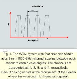
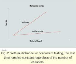
DWDM systems allow service providers to use more channels and tighter channel spacing-normally 0.8 nm (100 GHz)-to increase the capacity of existing networks without additional fiber. It is not uncommon today to see DWDM systems with 80 or more channels and 0.4-nm (50-GHz) wavelength spacing. By using multichannel test systems, the test time remains constant regardless of how many channels are added to the test process (see Fig. 2).
To perform concurrent testing on a 16-channel DWDM system, for example, optical splitters are used in both the transmit path and receive path to reduce cost (see Fig. 3). By employing four transmitters and splitting the optical signal using 1x4 couplers, the cost of 12 transmitters is saved. On the receive side, 16 receivers are placed in line with 1x2 couplers. This arrangement divides the signal so that it may be sent in parallel to both the receiver of the bit-error rate (BER) test set and to other measurement equipment-a sampling scope or an optical-spectrum analyzer, for example. Dividing the signal provides the advantage of simultaneously observing and testing the output.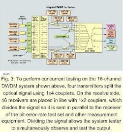
Optical attenuators are used in the transmit path to control the amount of power in a transmission channel. These attenuators, although commonly used during receiver sensitivity and overload testing measurements, may not be required because the splitters also attenuate power. In some cases, an optical amplifier is needed before the splitter to ensure the system being tested has adequate power.
Optical switches provide a convenient method for operators to route test signals to different types of measurement equipment easily and efficiently. Receive-side outputs from the 1x2 couplers link to a 16x1x4 optical switch for connection to any of the physical-layer measurement instruments.
The system shown in Figure 3 contains a sampling scope, an optical-power meter, an optical-spectrum analyzer, and an optical-wavelength meter for physical-layer testing. These instruments provide the following measurement capabilities used in DWDM testing environments:
- eye mask, extinction ratio, Q-factor
- channel spacing, channel power
- central frequency, spectral width
- average and total optical power.
Since BER is the primary performance parameter when the optical layer is terminated, testing at the Synchronous Optical Network/Synchronous Digital Hierarchy (sonet/sdh) client layer is sometimes even more important than the physical-layer tests. The most effective and accurate method of performance assessment in network applications is BER measurements at the data transport, which are most easily accomplished using sonet/sdh test instruments with BER measurement capabilities.
BER performance testing allows operators to accurately measure the error rate of a digital communications system. System testers must record a fairly large number of errors, however, to accomplish this verification. If n errors are counted, then the inaccuracy is about .
With multichannel systems, it is important to load all the operating channels to closely emulate actual conditions. Various traffic types stress different operating modes of the DWDM system. Patterns that emulate live traffic can help verify and guarantee required error performance. To emulate live traffic transport on a sonet/sdh system under test conditions, a pseudo-random bit sequence (PRBS) is used. A system that meets error performance objectives using pseudo-noise (PN23 or 223-1 PRBS) payloads helps ensure it will operate with the proper transmission quality.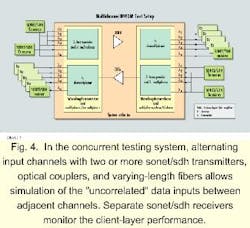
For improved margin testing, testers should use the PN31 (231-1 PRBS) pattern and bulk-filled payloads at OC-48c (2.4 Gbits/sec). The larger PRBS pattern will cross more multiframe boundaries to stress the DWDM system (see Fig. 4). But when testing BER performance using a PN31 pattern, more than 7 sec must elapse before the pattern repeats across multiframe boundaries. This procedure emulates live traffic across multiple frames more effectively.
The Table calculates the repetition times for the different PRBS patterns with a bulk synchronous payload envelope at OC-48c with 37,440 bits per frame.
Crosstalk is a major issue for multichannel communications systems. Because of the nonlinear effects in optical fiber and the linear nature of the demultiplexing elements, DWDM system performance decreases when a transfer of power from one channel to another takes place due to crosstalk. Crosstalk amplitude is directly proportional to DWDM channel spacing and affects BER measurements. To help characterize and monitor the effects of crosstalk, the following considerations are important:
- Use a PN31 pattern to emulate live traffic and stress multiframe boundaries.
- Take BER measurements at each receive channel with a fully loaded system.
- Take BER measurements at each receive channel when adjacent channels are added or dropped.
- Use uncorrelated stimulus; never connect the same transmit source to adjacent channels.
- Add varying lengths of fiber in series with any split transmit source, which will provide timing differences between channels to create uncorrelated stimulus.
In the multichannel testing system, alternating input channels with two or more sonet/sdh transmitters, optical couplers, and fibers of varying length allows simulation of the "uncorrelated" data inputs between adjacent channels (see Fig. 4). The use of "bulk-fill" payloads (OC-48c) and long PRBS patterns (PN23 or PN31) helps minimize test time and enables users to stress channel multiframe boundaries. Separate sonet/ sdh receivers monitor the client-layer performance.
Concurrent testing has advantages over loopback testing, another popular method of decreasing test times. With loopback testing, a transmit source and receive source produce a continuously looped signal. While significantly lower equipment cost is an advantage of this type of testing, its inherently limited testing abilities and inability to isolate errors and correct problems on individual channels may outweigh any savings.
Multichannel testing, on the other hand, allows system testers to independently validate and measure individual channel BER performance and isolate individual channel errors. By using multiple instruments, more control and flexibility are maintained in areas of individual testing. Testers can perform margin measurements on individual channels for different optical signal-to-noise ratios (SNRs). An SNR is an important parameter in performance variations and for crosstalk effects related to the power balancing between channels and the gain of erbium-doped fiber amplifiers in the system. The entire system can be monitored while channels are being added and dropped. Performance problems can be isolated to individual links with any B1, B2, or B3 error types.
The concurrent test system architecture described here is flexible and scalable. For other applications, system testers can vary the number of transmit sources and optical coupler configurations. Separate sources offer the most flexibility and guarantee uncorrelated data, but the cost is higher. A combination of two or more transmit sources and splitters provides a good exchange between signal flexibility and cost.
DWDM systems offer a viable, cost-effective solution to today's need for more bandwidth and ever-increasing speed. Using concurrent testing, operators can measure DWDM system performance with greater efficiency. To ensure proper DWDM system integration and operation, the following techniques and guidelines are recommended:
- Use concurrent testing to improve measurement resolution.
- Stress the DWDM channels across multiframe boundaries using bulk-fill payloads and PN31 patterns.
- Use concurrent testing to stress the system on a per-channel basis to identify margins and add/ drop channel effects.
- Maintain the ability to isolate performance problems on individual links with any B1, B2, or B3 error types.
- Balance cost-reduction considerations against multiple source signals to create a cost-effective, flexible testing station.
- Plan to use testing equipment with the ability to perform physical-layer measurements as well as BER testing.
Using concurrent testing, operators can monitor the entire system's performance and still isolate problems with individual channels. A flexible, cost-effective solution that allows testers to maintain testing control, concurrent testing is the best method for DWDM system measurement. u
Michael Farrell is an application engineer and Shelly Hazard is a technical publications writer for the broadband transmission test product line at Tektronix Inc. (Chelmsford, MA).

