HFC networks use noise power ratios to characterize optical components
This method requires care to ensure that errors are not introduced by preamplifier compression.
LAMAR WEST, Ph.D., Scientific-Atlanta Inc.
A popular technique for characterizing the performance of devices for use in sub-carrier multiplexed hybrid fiber/coax (HFC) networks is measurement of the noise power-ratio (NPR) curve. This approach is particularly effective for devices intended for reverse path (5 to 40 MHz). The technique involves loading the device with Gaussian noise containing a notch at a test frequency. The depth of this notch is measured with respect to the noise power as this noise power is varied over the operating range of the device under test (DUT).1
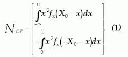
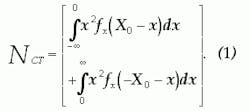
We assume the device is used in a reverse-path application and is loaded with Gaussian noise from 5 to 40 MHz with variance, &deltal2. We also assume the device produces its own noise power within the 5- to 40-MHz band at a fixed level of noise, N0. We can further assume the device produces distortion due to clipping of the output waveform and has unity linear gain below the clipping limits. The input noise may be described by its Gaussian probability density function (PDF), fX(x) .2 If we assume that our DUT hard limits at a value of ±X0, we may then calculate the total clipping noise power, NCT, at the output by:3Equation 2 assumes no compression of the input signal.
We use the techniques described by Mazo4 to determine the fraction of the total clipping noise power falling in-band, NCI. The Table shows the results of these calculations. The calculations were carried out for signal-to-NCT ratios ranging from 35 to 55 dB. Based on these results, we will use the approximation that one-half of the total clipping noise power falls in the 5- to 40-MHz band and that over this range it has a flat power spectral density. Doing so will result in a maximum error of -1.3/+1.21 dB over this range. The signal-to-noise plus in-band clipping noise ratio, S/(N0+NCI), may then be determined by:As can be seen, NPR is heavily dependent on the PDF of the input signal (Gaussian noise). If for some reason, the PDF of the input signal varies from Gaussian, the NPR curve may be significantly changed.
An over-driven preamplifier ahead of the DUT is one possible means by which a non-Gaussian PDF may be produced. Radio-frequency (RF) amplifiers of the type used in test setups for making NPR measurements tend to compress if driven at a sufficiently high level.5
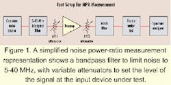
Consider such an amplifier loaded with Gaussian noise. At some point, as the level of the noise is increased, the amplifier will tend to compress the peaks of the noise waveform. Compression of these peaks will produce an output PDF that is no longer Gaussian in nature.A simplified NPR measurement block diagram is shown in Figure 1. A bandpass filter is included to limit the noise to 5-40 MHz. ATT1 and ATT2 are variable attenuators used to set the level of the signal at the input to the DUT. If the preamplifier is driven sufficiently hard, it may result in compression of the noise waveform. Such a condition may occur if the value of ATT2 is too large.
A numerical model was constructed to represent the setup shown in Figure 1. In the case of ATT1 and ATT2, we assume that the attenuators are perfectly linear with voltage gain g and 1/g, respectively. Their net effect on the signal level is unity gain. If presented with an input PDF, fX(x), their output PDF's, fY (y) will be given by:2respectively.
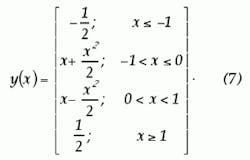
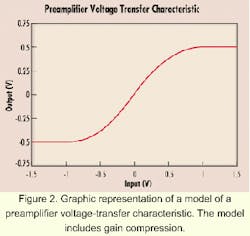
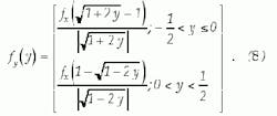
The preamplifier was modeled using a voltage transfer characteristic given by:By cascading the relationships given in equations 5, 6, and 8, it was possible to analytically determine the PDF of the signal at the input to the DUT. This PDF was then used to calculate the NPR of that device.
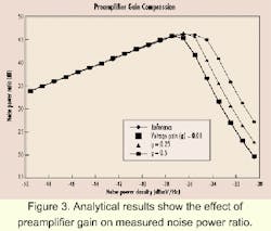
We chose the cascade of a high-speed analog-to-digital converter (A/D) and a high-speed digital-to-analog converter (D/A) as the DUT in our model. This configuration is similar to that used in digital reverse fiber-optic links for HFC networks. Exceeding the input dynamic range of the A/D produced two-level symmetrical clipping at ±0.5 V. The noise, N0, in our model results from the quantization error in the D/A-A/D. High-speed A/D converters produce quantization noise slightly greater than that predicted by calculations based on the actual number of output bits.6 Consequently, a parameter, effective number of bits (ENOB), is associated with these devices. N0 was determined analytically by calculating the power associated with a random variable whose PDF is uniformly distributed between ±1/2 least significant bit (LSB), assuming an ENOB of 8.67 bits. To confirm a particular test configuration does not cause any devices ahead of the DUT to affect the results, loss can be added at their output (and hence, force the devices ahead of the DUT to operate at a higher level) to thereby confirm the test results are unaffected.Figure 3 shows the effect of the value of g on calculated NPR. The same DUT was used as in the previous calculations (i.e., A/D-D/A back-to-back). Each individual curve is generated by varying the noise power level out of the Gaussian noise source (i.e., varying δ2) and recording the signal-to-noise plus in-band clipping noise ratio. The reference curve is calculated assuming a Gaussian noise signal at the input to the DUT. A different value of g and, consequently, a different amount of preamplifier compression, was chosen for each of the other curves. As mentioned previously, the two attenuators, ATT1 and ATT2, have gains g and 1/g, respectively, so that their net effect is unity gain.
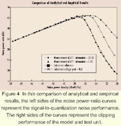
A test setup matching what is shown in Figure 1 was created in the laboratory. The DUT consisted of an actual high-speed A/D-D/A pair operating at 100 Msamples/sec. The noise power density (or the equivalent, δ2) was varied by varying the output power from the Gaussian noise source. As always, ATT1 and ATT2 were moved in tandem, such that their net effect on the amplitude of the noise applied to the DUT was zero. NPR curves were generated with ATT1=20 dB (very little preamplifier compression) and ATT1=0 dB (significant preamplifier compression).An overlay of empirical and analytical results is shown in Figure 4. The left sides of the NPR curves represent the signal-to-quantization noise performance. The right sides of the curves represent the clipping performance of the model and test unit. In both the analytical and empirical cases, the NPR and available dynamic range of the DUT exhibited apparent improvement as the preamplifier was driven into compression. The differences between the analytical and empirical results are likely due to our choice of model for the preamplifier.
Compression in a preamplifier may result in errors in an NPR measurement. Care must be taken with gain distribution when assembling an NPR test station to ensure that such compression does not adversely affect the test results. It is important to note that preamplifier compression may significantly affect the NPR results at levels far below those at which that compression results in a significant reduction of composite output power from the preamplifier.
In our empirical example, it was not possible to measure any effect on noise power at the input to the DUT using a Hewlett-Packard model 437B RF power meter, since ATT1 and ATT2 were adjusted in tandem over the ranges indicated above. However, a significant effect on the measured NPR was observed.
As a general rule, it is important to minimize the loss between any devices that are ahead of the DUT to ensure they are operating at the lowest possible levels. To confirm that a particular test configuration does not cause any devices ahead of the DUT to affect the results, it is possible to add loss at their output (and hence, force the devices ahead of the DUT to operate at a higher level) and confirm that the test results are unaffected.
Lamar West is a senior member of the Institute of Electrical and Electronics Engineers (New York City). Some information contained in this article is excerpted from IEEE Photonics Technology Letters, Vol. 12, No. 7, July 2000.
- O.J. Sniezko and T. Werner, "Return Path Components Test Methods and Performance Comparison," Proceed ings of the 1997 Conference on Emerging Technologies, Society of Cable Telecommunication Engineers, Jan. 8-10, 1997, pp. 263-294.
- A. Papoulis, Probability, Random Variables and Stochastic Processes. New York: McGraw Hill, 1965, pp. 100-101, 116-162.
- L.E. West, "On Determining the Optimum Modulation Index for Reverse Path Lasers in Hybrid Fiber Coax Networks," IEEE Photonics Technology Letters, Vol. 8, No. 11, pp. 1555-1557, November 1996.
- J.E. Mazo, "Asymptotic Distortion Spectrum of Clipped, dc-Biased Gaussian Noise," IEEE Transactions on Communications, Vol. 40, No. 8, pp. 1339-1334, August 1992.
- Motorola RF Device Data Book, DL110, Rev. 5, Copyright 1994, Motorola, Inc., pp. 3-139 - 3-170.
- Data Sheet, "AD9071, 10-Bit, 100 MSPS A/D Converter," Copyright 1998, Analog Devices Inc., Norwood, MA.
