Options for high-speed transmission on mixed-grade fiber plant
There are several alternatives for addressing polarization-mode dispersion, depending on the application.
Rich Moran
YAFO Networks
DWDM has proven a great enabler of more bandwidth on fiber plant. Since about 1995, the long-haul backbone fiber plant of most carriers has gone from a single wavelength per fiber up to about 100 wavelengths per fiber, with systems promising 160 to 200 wavelengths planned for next year. At the same time, faster time-division multiplexed (TDM) systems have also provided room for growth. The standard of 2.4-Gbit/sec SONET/SDH systems for new deployments in 1995 has evolved largely to 10-Gbit/sec SONET/SDH for new systems deployed today.
The introduction of 10-Gbit/sec transmission has been especially beneficial to enabling packet-based traffic. With its very fast growth rate, Internet Protocol (IP) traffic had been particularly constrained by TDM line rates of 2.4 Gbits/sec and less. Now, core routers with OC-192c (10-Gbit/sec structured to allow long concatenated IP packets) interfaces are well equipped to handle the heavy growth and periodic spikes in IP traffic demand in the core of today's networks.However, systems with 10-Gbit/sec TDM transmission rates have been limited by some issues in the fiber plant of many networks. One major issue in some older fiber systems is polarization-mode dispersion (PMD). To overcome the effects of PMD that would limit the performance of the network, three alternative solutions have emerged.
A major cause of PMD is the asymmetry of the fiber-optic strand. Fiber asymmetry may be inherent in the fiber from the manufacturing process, or it may be a result of mechanical stress on the deployed fiber. The inherent asymmetries of the fiber are fairly constant over time, while the mechanical stress due to movement of the fiber can vary, resulting in a dynamic aspect to PMD.
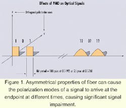
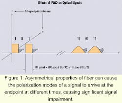
The asymmetry of a particular fiber affects the optical signal in that fiber, and its effect is different for each polarization mode of optical energy within the fiber (see Figure 1). The asymmetry causes the polarization modes of the optical signal to propagate at different velocities. This difference in velocity means that the polarization modes of each bit in the optical signal arrive at the destination-the receivers-at different times.In long fiber spans, enough PMD can accumulate, so bits arriving at the receiver begin to interfere with one another, degrading transmission quality. This problem becomes more pronounced as transmission rates get higher because bit periods get shorter, increasing the likelihood of sequential bits interfering with each other and causing the receiver to misread the optical signal.
The effect of the different velocities of propagation is measured in time units of delay; the delay is the difference between the arrival time of the faster mode of polarization at the receiver and the arrival time of the slower mode. Generally, PMD delays greater than 10% of the transmission bit period are considered detrimental to the quality of the transmission. PMD can become significant at 10-Gbit/sec transmission rates, since the bit period is only 100 psec at this speed.
At 40 Gbits/sec, the potential for PMD-related errors at the receiver increases greatly, since the transmission bit period is only 25 psec and therefore the PMD tolerance is only about 2.5 psec for non-return-to-zero (NRZ) transmission. Since PMD can be caused not only by the fiber, but also by components in the network used to split, combine, amplify, or otherwise modify optical signals, PMD is expected to be a significant and growing concern in 40-Gbit/sec system implementations. Overall, the more elements in the network that manipulate and groom the optical signal, the more potential there is for PMD-related factors to cause degradation of the transmission-signal quality.Another aspect of PMD is its variability over time. Diurnal heating and cooling, vibration from passing vehicles, fiber movement in aerial spans, and cabling disturbances by craftspeople (e.g., during patch-panel rerouting) have all been shown to affect PMD. These events can momentarily increase the PMD in a fiber span and briefly affect the transmission quality of an optical signal on that span. Since the effects are momentary, the system problems are hard to isolate and diagnose. These types of problems are sometimes known as "ghosts," because they occur mysteriously and then disappear and cannot be replicated during a system maintenance window.
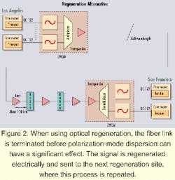
Since PMD is a function dependent on the distance of the optical-transmission span, one way to address PMD is simply to shorten the span distance. Let's say the optical network needs to support an OC-192c interface between two core routers: one in Los Angeles and one in San Francisco. Starting with the optical interface on the core router in Los Angeles and traveling to San Francisco over a 600-km distance, the optical span can be terminated every 200 km or so before the signal degrades due to PMD (see Figure 2). At each termination point, the optical signal is regenerated, that is, made into an electrical signal and then into a new optical signal for transmission along the next span. This "shortening" of each fiber span limits the effects of PMD sufficiently so that the OC-192c signal arrives clean and error-free at the destination point 600 km later in San Francisco.
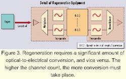
In a 10-Gbit/sec DWDM system with multiple wavelengths, regeneration of the optical signal is performed on each wavelength independently. As shown in Figure 3, the multiplexed signal must be demultiplexed before regeneration. Then each OC-192c signal must be converted separately to an electrical format, converted back to optical, and multiplexed with other wavelengths and transmitted to the next regenerator site.
Regeneration of the optical signal was a widely used approach on all optical-transmission systems until the advent of optically amplified DWDM systems in the mid-1990s. Regenerators used before that time not only limited PMD, but also boosted the power level of the optical signal. However, once multiple wavelengths appeared on long-haul fibers with the introduction of DWDM, the deployment of optical amplifiers replaced the use of regenerators for boosting signal power. Optical amplifiers operated across multiple wavelengths and offered an economical optical alternative to electrical regeneration. However, amplifying the optical signal does not reduce PMD and in fact may increase it. Therefore, amplification alone is not an option on fiber spans with high PMD.
"Inverse multiplexing" is a generic term for the transport of a signal from a subscriber across multiple paths in the network at a lower bandwidth rate than it was received from the subscriber. A common example of inverse multiplexing is an application that has been around for many years in the access network: the transport of 10-Mbit/sec Ethernet links across multiple DS-1 transmission paths. Since the hierarchical, legacy access network had no transmission bandwidth choices between DS-1 at 1.5 Mbits/sec and DS-3 at 45 Mbits/sec, subscribers wanting a full 10-Mbit/sec pipe between two points would effectively "disassemble," or inverse multiplex the signal, before transmission on the network. The inverse multiplexing would often take place at the subscriber premises, in a bridge or router device controlled by the subscriber. Then, at the distant-end subscriber location, the signal would be reassembled.
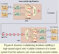
Inverse multiplexing for support of 10-Gbit/sec services operates in a similar manner (see Figure 4). In this case, the subscriber's service is the OC-192c transmission from the core router; it is disassembled for transport across the network by the inverse-multiplexing device. An OC-192c service could be disassembled into 2.4-Gbit/sec "chunks" for transport, then reassembled at the destination point and handed off to the destination core router. Since PMD is less of an issue at 2.4 Gbits/sec, inverse multiplexing provides a "workaround" solution for moving 10 Gbits/sec across a fiber network with PMD issues.
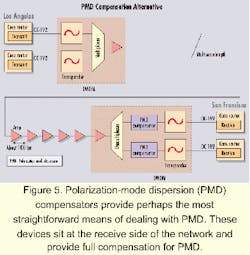
Compensation for PMD fixes the optical signal before it is read and interpreted by the receiver at the end of the fiber path (see Figure 5). Compensation methods for PMD have been explored since the potential bandwidth limitations of PMD were first recognized in the mid-1990s. However, early generations of PMD compensators were limited in performance, addressing only a small range of PMD.There are both somewhat "static" and "dynamic" aspects to PMD; a PMD compensator must mitigate the effects of both. In addition, the dynamic effects of PMD further break down into "slow" effects (e.g., day-to-night heating and cooling) and "rapid" effects (e.g., fiber-jumper disturbances). To address these different types of effects requires a dynamic, adaptive element.
Newly available PMD compensators are superior to early versions in their ability to handle a wider range of PMD events. Their performance is enabled by their intelligence-a qualitative analysis and control of the compensating device. This analysis and control algorithm must be fast and reliable as well as economical. Recent advances in digital signal processors (DSPs) have permitted the latest PMD compensators to meet these criteria.
There are advantages and disadvantages associated with each of the three options. Regeneration is likely the most widely deployed option in networks to date. A primary reason for regeneration's deployment is that, for some time, it was the only alternative: both inverse multiplexing and PMD compensation are just now becoming available to carriers at 10 Gbits/sec.
But as is typical with many new options, both inverse multiplexing and PMD compensation can offer better economies than regeneration. To understand the cost issue, we can examine the typical regenerator system in Figure 3. Because the equipment at each regeneration site is essentially a duplicate of the equipment at both endpoints of the 10-Gbit/sec system, each regeneration site adds about 100% to the cost of an end-to-end system without regeneration. Therefore, a 600-km end-to-end system with two regeneration sites would be about three times the cost of a system without regeneration.
Regeneration provides other benefits in addition to eliminating concerns about PMD, primarily boosting the optical signal. But since regeneration, and therefore the cost of regeneration, is wavelength-specific, the economics of regeneration worsen as more channels are added on each fiber. For this reason, end-to-end systems that do not exhibit PMD problems utilize optical amplifiers to replace regenerators to boost the power of the optical signal.
PMD compensation, like regeneration, is performed on a per-wavelength basis. However, a single PMD compensator at the receive side of a 10-Gbit/sec signal can mitigate the PMD effects that build up over an entire transmission span. Therefore, unlike the regeneration option, which may require two separate sites to eliminate PMD on a 600-km span, a single PMD compensator located at the destination or receive side of the optical signal can improve the end-to-end performance of the transmission path.
PMD compensation can be accomplished for a fraction of the cost of a single regeneration site's equipment costs. In addition to the equipment costs associated with regenerating optical signals, there is also the issue of the costs of the regenerator sites themselves. Since these sites must be located within certain distance ranges along the optical-transmission path to operate most effectively, the required placement for these sites may often be in difficult geographic locations. The buildings to accommodate these sites are often more costly to construct and maintain than equivalent real-estate space in the most desirable urban locations, simply because the site is so remote.
Like regeneration and PMD compensation, inverse multiplexing is also accomplished on a per-wavelength basis. It is performed at the electrical level after an individual wavelength of an OC-192c optical signal is transformed into an electrical signal. The demultiplexing, or disassembly, of the OC-192c signal is performed either in the transponder stage of a DWDM network element or in a multilayer optical router/crossconnect, which may groom and route traffic at the optical layer (Layer 0), the transport layer (Layer 1), and/or the switching/routing layers (Layers 2 and 3).One generic advantage of an optical router/crossconnect is its ability to quickly provision an end-to-end connection across a network. To provide an end-to-end OC-192c connection via inverse multiplexing, the optical router/crossconnect would have to provision four 2.4-Gbit/sec wavelengths across a network, thereby providing the same bandwidth as a single 10-Gbit/sec pipe.
One drawback to the inverse-multiplexing approach: There is no current standardized process for the disassembly and reassembly of the OC-192c signal. Therefore, at the endpoints of the OC-192c signal, where in our primary example, the concatenated packets from a core router are disassembled (inverse-multiplexed) in Los Angeles and re-assembled in San Francisco, the same vendors' element must be deployed at both locations for the application to work.
Multivendor inverse multiplexing is likely to be achieved over time, however, through a combination of the initiative of individual vendors and the standards efforts of organizations like the Optical Internetworking Forum (OIF) and Optical Domain Service Interconnect (ODSI) alliance. A similar effort at standardization was achieved in 1997 by the ATM Forum with the ATM Inverse Mux standard, primarily for the transport and handling of ATM 25-Mbit/sec signals over DS-1/E1 links at the network level.
Another potential drawback to inverse multiplexing: Four signals (at 2.4 Gbits/sec) must be carried across the network with this approach as opposed to carrying a single 10-Gbit/sec signal. In a DWDM system, these four signals would each occupy a wavelength, and the DWDM system would reach capacity exhaust more quickly.
In addition to the network-capacity issues, the four separate inverse-multiplexing signals are inherently more prone to a failure of some kind than a single 10-Gbit/sec signal, all things being equal. But if the four signals are provisioned through an optical router/crossconnect element, there may be some function within this element for fast restoral of failed signals. Still, since we are focused on the application of the transport of IP packets within the OC-192c payload, these packets can usually be retransmitted (through Layer 3 operations) without a noticeable impact on the application layer. Therefore, restoral and reliability may be a lesser issue than if we were focused on the transport of a non-fault-tolerant application like voice or live video.
The overall trend of networking is to place more and more function at the optical level; of the three options, PMD compensation is the most consistent with this trend. As optical signals are being routed, switched, and even offered directly to subscribers on a wavelength-by-wavelength basis, there is real value in implementing solutions that improve the quality of the transmitted optical bit. PMD compensation directly addresses the effects of PMD, no matter what the cause.
The best solution for 10-Gbit/sec transport on PMD spans is, as is always the case, dependent on the application. Shorter routes may be economical for regeneration, the most widely deployed approach. Multifunctional optical routers/crossconnects, deployed for quick provisioning, can work around PMD with inverse multiplexing. Finally, PMD compensation offers an end to workarounds and a solution not only for 10 Gbits/sec, but also for 40 Gbits/sec and beyond.
Rich Moran is director of product marketing at YAFO Networks (Hanover, MD). He can be reached at [email protected].
