Combating dispersion effects with linearly chirped fiber Bragg gratings
Myo Ohn E-TEK ElectroPhotonics Solutions
John E. Donohue ADC Broadband Communications
With the advent of long-haul high-cap acity systems operat ing at high speeds, chromatic-dispersion effects can be a real problem. Dispersion effects occur as different wavelengths in a signal propagate at different speeds along the optical fiber. The problem is exacerbated in high-speed dense wavelength-division multiplexing (DWDM) networks because they rely on wavelengths in the 1,550-nm window, where dispersion is high.
To combat harmful dispersion effects, dispersion compensation in optical links has become mandatory and hence widespread. One emerging application requiring dispersion compensation is in the extension of a cable-television optical link while maintaining existing digital-video (DV) headend equipment.
We'll describe the performance measurements of dispersion compensators that were used to extend optical links beyond the original link-length budget. Two types of dispersion compensators were compared: linearly chirped fiber Bragg gratings (LCFBGs) and dispersion-compensating fiber (DCF) modules. The results showed that both dispersion compensators worked as intended, with the grating compensator outperforming the dispersion-compensating fiber module in four-channel DWDM systems and providing better pricing for comparable performance.
The most common method of combating the effects of anomalous chromatic dispersion (CD) in the vast installed base of ordinary, nondispersion-shifted fiber (NDSF) is DCF. DCF is a specialized fiber that has high levels of negative dispersion over relatively short lengths. It has the ability to offset the positive dispersion accumulated by a pulse traveling on standard singlemode fiber. A few kilometers of such specialty fiber can be placed at specific links in a long-distance network, typically at the receive end. Because of its maturity, DCF is currently the only fully accepted method of CD management deployed in multiwavelength, long-haul, and high-bit-rate systems.
The characteristics of DCF have been extensively investigated and the merits are well known. The primary advantage of this all-fiber component is its large optical bandwidth, making it cost-effective for the bulk compensation of multiple optical carriers that are spread over the entire C-band (1,530 to 1,565 nm) according to the International Telecommunications Union (ITU) grid. Though this feature is highly attractive, there are significant disadvantages that have prompted designers to look for other improved and emerging technologies.
The launch of multiple optically amplified DWDM channels into a DCF's small core at an optical-amplifier site reveals one of the technology's severe shortcomings. Noise generating, nonlinear effects, such as SPM and XPM, develop and induce large eye-power penalties. This is because DCF has half the mode-field diameter of ordinary NDSF and a higher nonlinear coefficient (n2). With the same amount of launched in-fiber optical power, the power density within the core of DCF increases by 16-fold compared to that of NDSF. It is therefore imperative that transport network engineers become cognizant of the channel count, total power density, amount of amplification, and placement of DCF as important parameters when designing DCF into the fiber link.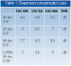
Another inherent drawback is the dispersion slope associated with DCF. Typical NDSF has a dispersion slope of 0.09 psec/nm2 compared to -0.15 psec/nm2 for DCF. As the two dispersion-slope values are not matched, a difference in CD between the extreme ITU channels of the C-band results. For short-haul DWDM metropolitan-area networks, this net CD is small and not an issue in regards to exceeding the dispersion tolerance of the receiver. However, in long-haul, multiple-span, point-to-point OC-192 networks with amplifier sites (fitted with optical-line amplifiers and DCF) spaced 80 km apart; the net dispersion between the extreme channels of the C-band is likely to be beyond the dispersion tolerance of the receiver. For example, in a seven-span link, the net CD is approximately 800 psec/nm at 1,557 nm for exact compensation at 1,533 nm.
Another disadvantage of DCF is its high attenuation. At 0.6 dB/km (three times that of NDSF), a total optical loss of 10 dB can be incurred for a 17-km DCF module, meaning that the use of DCF takes up slightly more than one-third of the typical 28-dB power budget allocated per span. Taking all these issues into account, it becomes necessary to seek alternative technologies for dispersion compensation.
One attractive technology for dispersion compensation is the LCFBG. The tendency of fiber Bragg gratings (FBGs) to optically disperse arises from the wavelength-dependent group delay caused by the linearly varying Bragg condition along the length of the grating. Simply stated, different wavelengths are reflected from different portions within the in-fiber grating structure. To combat anomalous CD, the local wavelength-reflection point is simply a linear function of distance (longer wavelengths are reflected before shorter). By tailoring the grating pitch of the FBG along the fiber device to a predetermined design, the intended dispersion profile can be attained.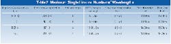
In principle, a dispersion slope of (0.09 psec/nm2 could also be designed to match the third-order CD of NDSF and be used to eliminate the accumulated residual dispersion. The FBG can compensate either for normal or anomalous chromatic dispersion by launching into the short or long wavelength end, respectively. With a typical in-band maximal insertion loss of 0.5 dB per DCG, the total insertion loss of the device becomes <2 dB with a 3-port circulator, a savings of about 6 dB in optical power compared to DCM80. The reclaimed optical power will benefit an optical link in two ways: it will allow either approximately 20 km of further propagation or it will yield lower noise figures due to reduced optical amplification in the span. Ultimately, this translates into reduced equipment costs.
The dispersion in LCFBG devices is imparted during the fabrication process and is designed to be within a certain tolerance of the required compensating value. After manufacture, these devices are packaged so as to provide both environmental and thermal stability. A variety of dispersion compensating gratings (DCGs) is implemented as fixed, passive CD compensators.
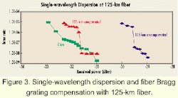
Recently, a number of applications of DV equipment have surfaced, requiring optical links exceeding the 100-km rating for standard and DWDM DV transmitters. An extended-range DV transmitter is available, permitting single-wavelength links of 130 to 145 km. But for transporting multiple DWDM wavelengths, dispersion limits the link lengths to 100 km or less, regardless of loss or received power.
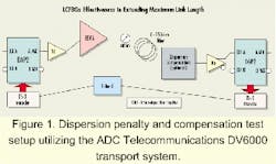
In a recent experiment by ADC Telecommunications, an HX8170AM 17-dBm erbium-doped fiber amplifier (EDFA) was used with 2.5-Gbit/wavelength DV-6000 equipment and direct-modulated digital lasers (see Figure 1). The purpose was to determine the effectiveness of LCFBGs in extending the maximum link length of a fiber backbone.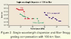
In a multichannel DWDM optical link, the loss limits imposed by the combination of DWDM modules and the dispersion compensator significantly affects the choice of dispersion compensator. Table 1 illustrates the typical loss versus compensating value tradeoff of the DCF module and LCFBG.
The single-channel 80-km DCM has a typical loss value 5.8 dB better than its DCF counterpart. A four-channel DCM based on an LCFBG (see Figure 5) can offer a low insertion loss of 2.5 to 4 dB per channel (with a uniformity of typically 1.5 dB). This also translates to an approximate savings of about 4 dB compared to 80 km of DCF.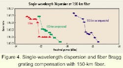
Table 2 shows the maximum link length and cost versus number of wavelengths in the link, using a single 17-dBm EDFA, as well as nominal performance parameters for the fiber, EDFA, and compensators. In every case, the loss budget is the limiting parameter. The analysis does not take into account gain slope and other loss factors found in the test, which will further reduce the maximum link. Table 2 illustrates that the fiber Bragg grating compensator provides greater link capability, by virtue of its lower loss, at lower cost. With four wavelengths, the fiber Bragg grating compensator yields a 10-km longer link than dispersion-compensating fiber modules.
Most applications for EDFAs in DV systems are for extending single links beyond the 100-km limit of standard singlemode fiber and DWDM DV transmitters. In these applications, dispersion compensators must be employed.
The choice of using LCFBG or DCF modules depends primarily on the number of wavelengths to be transported. For four wavelengths, LCFBG-based modules provide superior performance and price. Link lengths of 150 km or more can be achieved in this way, using gratings rated to compensate for 80 km of fiber. Where more than four wavelengths must be transported, multichannel LCFBG-based dispersion-compensation modules can be used, with effective cost reductions that provide further price competitiveness. Although insertion losses tend to be higher with higher-channel-count LCFBG modules, the inherent nonlinear effects produced in DCF modules are nevertheless avoided.
Myo Ohn is market and product manager at E-TEK ElectroPhotonics Solutions (Markham, ON, Canada). John E. Donohue is principal electrical engineer at ADC Broadband Communications (Wallingford, CT).