Advanced comb source provides improved EDFA/DWDM system test
David Zhuang and Stephen Bennett ILX Lightwave
Lee Branst Caracal Communications
Dense wavelength-division multiplexing (DWDM) systems and erbium-doped fiber amplifiers (EDFAs) are becoming commonplace for communications as we enter the new millennium. Yet their impending ubiquity creates its own challenges. One challenge revolves around evolving test requirements.
Since their introduction in 1997, modular DWDM laser sources have become indispensable in the development and production testing of EDFAs and DWDM systems. However, recent market shifts and the rapid evolution of test requirements have created a demand for increased capabilities in the test platform. Thus, any new platform must address three paramount issues: test-system cost, production throughput, and product specification/performance tolerances.
An advanced comb source (to be demonstrated at OFC 2000) should help to redefine value-added test solutions for EDFA, DWDM system, and passive component suppliers in the new millennium. We'll detail the evolution of market and test requirements for EDFA and DWDM systems and describe an advanced comb-source platform.
Existing modular laser-source platforms, with 8-16 distributed-feedback (DFB) laser-source modules in a rackmount mainframe, were designed as cost-effective, high-channel count, DWDM source platforms for testing EDFAs and EDFA-based DWDM systems, particularly in a space-conscious production environment. By providing lower cost, smaller footprint, and easier integration than user-configured arrangements of individual benchtop test components, such platforms have assisted ably in the phenomenal growth of the EDFA/ DWDM market segment.However, the various market forces that shape this market segment are changing rapidly. EDFA and DWDM system suppliers have been under tremendous pressure to reduce costs to remain competitive. For example, today's telecommunications market has shown similarities to the silicon economy, which has become known for its annual downward price spiral of around 30%. Thus, to defend their profit margin and avoid vicious price wars, most EDFA and DWDM system suppliers have opted for increasing the value of their products through product differentiation.
Improving performance specifications is a favorite option toward this objective. Under many circumstances, product-specification improvement relies on the availability of feasible test solutions to validate new designs and to verify performance at the production line. The characterization of the polarization-dependent performance of EDFAs is but one example.
In addition, depreciation costs of production can contribute about one-fifth of the total EDFA production cost. Thus, manufacturers are looking to test equipment suppliers to assist in the reduction of depreciation costs.
Bandwidth demand that has outperformed even the most optimistic forecasts presents another source of pressure on EDFA and system manufacturers. This explosive growth has greatly accelerated the pace of channel-density increases (moving toward 50-GHz spacing and beyond) and channel data bit rate (where 10 and 40 Gbits/sec per channel are no longer unthinkable). Thus, EDFAs and EDFA-based DWDM systems will need to be capable of increasingly demanding performance.
As a result of all these factors, the deployment of value-added test solutions naturally has become an investment focus of EDFA and DWDM system suppliers. To keep pace with manufacturers' needs, fiber-optic test and measurement equipment suppliers will need to rethink their next-generation test platforms to help customers significantly reduce their production costs and improve product specifications.
Since its market introduction in 1997, the modular DWDM source platform has evolved into a test platform that may include not only source modules but also other value-added modules, such as optical switches, optical attenuators, and optical power meters. The user interface provided via both the front panel and GPIB/RS-232 technology also has advanced to meet the needs for system integration and convenient operation. Features generic to a modular DWDM source platform are summarized in Table 1.
Compared with a test system based on bench-top instruments for EDFA and DWDM system testing, the modular DWDM source platform is easier to use and provides more flexible performance. For example, both the source modules and the mainframes that hold them can be linked to accommodate increased channel density and allow control via a single GPIB address. Modular platforms now provide increased performance power, wavelength stability, and wavelength tuning. Value-added functions and modules can address such issues as power attenuation and coherence control. Such platforms provide all these features in a compact, low-cost package that lessens requirements for user-supplied equipment and cabling.
All indications are that the DWDM telecom market is moving towards higher channel count (>64), so test systems must do likewise. The modular DWDM source platform is an excellent solution for 8-16 channels compared to bench-top sources, because of its lower cost, reduced space, and easier integration. Large channel counts, however, are a challenge for today's modular source platforms due to the following:
- Cost per channel has not kept pace with system test cost drivers.
- Integration of large systems can be difficult and time consuming.
- Channel equalization is easy with 8 or 16 channels but time-consuming for >40 channels.
- It is difficult to integrate additional functions, e.g., polarization alignment.
- Space requirements per channel become significant.
To improve upon the capabilities of currently available modular DWDM source platforms and keep up with the rapidly progressing market, suppliers of test platforms must focus on several issues. For example, they must find a lower-cost way to provide DWDM sources. For example, by integrating more than 16 channels, the cost per channel should decrease. Meanwhile, they must enhance source capabilities, such as:
- Accommodate up to 40-mW output per DFB source (as these devices become available).
- Permit wider DFB tuning without compromising other specifications.
- Integrate various modulation options.
- Provide faster wavelength and power stabilization while simultaneously adjusting output power.
- Operate across the normal production environment.
An automatic channel power equalization option, which provides an integrated shutter for each channel and single-command, fast power equalization, would also prove useful. So would easier system integration for customers, including:
- Single rack-mount box containing all source channels in smaller space.
- Integration up to full C-, L-, and S- band at 50-GHz spacing.
- Substantially fewer customer optical interconnections.
- Front or rear optical and electrical I/O.
- More optical devices in the chain, connected and ready to go.
- Split power to feed more test benches and further reduce costs.
- Ability to accommodate customer-supplied and/or customer-installed laser diodes.
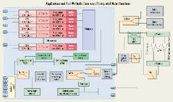
One solution toward meeting today's stringent EDFA and DWDM system testing requirements may be found with the help of the advanced comb-source platform (see Figure). Generally, a comb source is formed by a group of evenly spaced DFBs, each on its own particular International Telecommunications Union or customer-selected wavelength. A mechanism may be applied to compensate for disturbances that may cause wavelength drift, thus locking each DFB at its designated wavelength over time. When viewed on an optical spectrum analyzer, the DFB signals may appear similar to the teeth of a comb, hence the name.
The advanced comb-source platform is a full-rack-width enclosure capable of holding up to 48 DWDM DFB source modules. It can also integrate optional user-supplied instruments or functions, including optical multiplexer, wavelength reference, variable optical attenuator, and external optical power-measurement modules. It can be configured to source several test stations by splitting output power, and provides flexible modulation capabilities for small/ large signals and internal/ external sources.
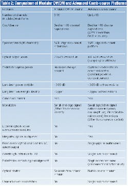
Table 2 compares the capabilities of the modular DWDM source platform and the advanced comb-source platform. The features offered by the advanced comb-source platform appear to serve high-channel-count (>24) test applications well, where lower cost, easier integration, and broader test capability are essential.A great part of the utility of an advanced comb source is its ability to perform complex tests for EDFA and DWDM system by providing near-real application simulations. It must be able to perform a number of specialized tests, including those listed in Table 3.
The rapid market progression and change of test requirements for EDFA and DWDM system development and production have redefined the playing field for fiber-optic test and measurement instrument/solution suppliers. High-channel-count test platforms/ solutions will need to meet the challenge of delivering lower cost, easier integration, and broader test capabilities. The advanced comb- source platform, as a natural evolution of the modular DWDM source platform, appears to meet many of these requirements.
"Fiber Test Equipment Meets Increasing Telecommunications Challenges," David Zhuang and John Powers, Photonics Spectra, May 1998.
David Zhuang is an independent consultant and was the director of product planning for ILX Lightwave (Boulder, CO). He can be reached at (720) 890-0114. Stephen Bennett is an electro-optical physicist and product marketing manager at ILX Lightwave and can be reached at (303) 516-8879. Lee Branst is a marketing-communications consultant and can be reached at (310) 542-4233.An advanced comb-source platform must provide excellent value while meeting increasingly stringent requirements for testing current and future EDFA and DWDM systems. As a result, an advanced comb source should integrate the following major functions: per-channel polarization control/scramble; wavelength referencing to ITU-T grid; internal and external modulation to 2.5 GHz; output power splitting; per-channel shutter; optical power-measurement module; telemetry channels; variable optical attenuator; powerful user interface; and a waveguide multiplexer. The diagram shows one possible arrangement of components and functions.


