All-optical networks: How to get there in stages

Service providers can react to market demands using a phased approach to evolving their traditional DWDM network architectures to an all-optical network.
Today, interexchange carriers (IXCs) face unprecedented bandwidth demands, the need for same-day circuit provisioning, increasing operations and maintenance complexity, and the escalating cost of network builds. Widespread traditional dense wavelength-division multiplexing (DWDM) networks have fundamental technology and architectural limitations that prevent carriers from addressing these challenges. Many carriers have recognized the shortcomings of their existing DWDM architectures.
DWDM was first introduced in the long-haul network and is now being applied to the metro and access portions of the optical network. Hybrid ring-based Synchronous Optical Network (SONET) and DWDM systems are not providing the provisioning velocity or the cost reduction and scalability that carriers need to reduce the cost-per-bit of high-speed OC-N channels.
All-optical networks offer technology and architectural attributes that address these critical issues. Carrier-grade, all-optical networking inherently redelivers capabilities that overcome traditional DWDM limitations, increase overall system performance, enhance competitiveness, and drive down costs. The required capability includes amplifiers that support ultra-long distances without regeneration, optical routers that transparently route wavelengths and scale to multiple terabits, high-capacity DWDM terminals, transparent optical add/drop systems, and associated all-optical network management systems.
To understand how an all-optical network can address many of the challenges that IXCs face as bandwidth and service demands escalate, it is important to first understand the limitations of traditional DWDM architectures.
IXCs first deployed DWDM in response to bandwidth demands, as a way to provide dramatic capacity increases over time-division-multiplexing (TDM) systems. DWDM systems were implemented using point-to-point topologies. Typically, this route is linear, with regeneration sites, terminals, and intermediate drop sites. As customer demand increases in both capacity and geographic extent, the point-to-point topology is extended through multiple overlays and interconnections.
The simplicity of this topology underlies its strengths and its weaknesses. Carriers can increase capacity above a single channel. It is also well understood and easily deployed. At the same time, however, it presents operational and business problems.
IXCs face escalating capital costs as they add back-to-back regenerators every 400 km to 600 km for each customer circuit. This cost increases as the customer circuits become longer. In many networks, more than 50% of the customer circuits exceed 3000 km, according to research from RHK Inc.
With traditional DWDM architectures, regenerators need to be installed and turned up for each customer circuit at each regenerator site. Therefore, the speed of provisioning end-to-end customer circuits is limited by the turn-up of channel regenerators every 400 km to 600 km. Turning up an OC-48 (2.5-Gbit/sec) or an OC-192 (10-Gbit/sec) customer circuit can take from four weeks to four months. Although this provisioning speed can be improved with "preprovisioning" of the regenerator stacks, this can be a disaster financially and results in stranded capital.
Another concern for carriers is escalating operations costs caused by the complex maintenance, power, and vast floor-space consumption associated with multiple per-channel regenerators. This problem becomes even more acute with the colocation huts on swapped fiber routes.
Scalability of the network is also complicated. This point-to-point system can expand in one of two ways. Growth can occur linearly, for example, when two point-to-point systems are simply interconnected. This linear expansion is sometimes referred to as a degree-2 interconnection.
Growth can also occur in a mesh topology when more than two point-to-point systems need to be interconnected. This interconnection is referred to as a degree-3. Degree-4 interconnection scenarios--and higher--frequently occur.
At each interconnection point, the service provider has an opportunity to pick up local traffic, terminate traffic, or perform electrical regeneration of transit (express) circuits. While this infrastructure expands the scope of the network, it also extends the service providers' operations and business problems across a larger geographic area.
Most service-provider networks consist of a large number of these interconnection points or hubs. With traditional DWDM networks, these interconnection hubs require that each DWDM channel be physically terminated. Although as a concept, physical termination of all circuits seems relatively straightforward, it is expensive and operationally complex.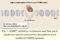
Carriers have recognized this complexity and instituted several methods of automating this task at hub sites--through the use of sophisticated fiber-patch panels, traditional crossconnects, SONET add/drop multiplexers (ADMs), and next-generation electrical crossconnects (see Fig. 1). This approach allows carriers to enhance connectivity, handle local traffic, and provide data/DS-x/OC-N bandwidth grooming capability.
Performing interconnection in this manner, however, has numerous downsides. The following limitations could pose problems for service providers:
- Inability to rapidly provision new circuits on an end-to-end basis without physical termination at the interconnection sites.
- Operational complexity of managing a fiber maze, where customer circuits are manually "patched through" from one DWDM terminal to the other.
- Added cost of physically terminating each channel and deploying a minimum of a single pair of "interface" cards for each circuit as it is sent through the interconnection device. This problem is especially true as both the working and the idle/protection circuits are extended into the thousands of kilometers, since these circuits encounter multiple interconnect hubs along the way.
- Cost and complexity of expansion caused by overlay builds of hub crossconnect systems, which do not scale easily--and the subsequent circuit churn management.
Several technology, architecture, and network-management capabilities are required to overcome the limitations encountered in traditional DWDM systems. The elimination of regenerators over ultra-long distances reduces network cost and complexity. Carriers also need the ability to seamlessly scale bandwidth by utilizing the full signal spectrum without the degradation caused by fiber nonlinearities.
The flexible handling of both OC-48 (2.5-Gbit/sec) and OC-192 (10-Gbit/sec) speed circuits is another requirement. The ability to add and drop optical signals while transparently (without conversion to electrical signals) passing through the rest also lowers cost. Any optical solution that can deliver on these capabilities offers service providers immediate business benefits, as indicated in the Table.
An all-optical network that supports the characteristics listed in the Table require the following equipment:
- Optical amplifiers that deliver scalable terabit capacity through full use of the optical signal spectrum
- OADMs that transparently add and drop channels up to the maximum capacity of the fiber
- Optical routers that are scalable in switching capacity at interconnection sites while still allowing for grooming and termination of local traffic
- Optical terminals with terabit capacity accessible through open and standard interfaces
- Network-management software that supports rapid and real-time circuit provisioning and the ability to graphically define and provision circuit restoration and protection routes.
Carriers can obtain the benefits of an all-optical network, even if they deploy these capabilities in phases. Such an approach would typically start with an ultra-long-haul point-to-point architecture. Next-generation crossconnects can serve as interconnection vehicles at hub sites. The next phase is the identification of intermediate drop points on the network, which will be upgraded to transparent OADMs. Finally, these transparent OADMs are replaced with all-optical routers to handle degree-3 (or higher) interconnection. The completion of these phases results in an all-optical mesh architecture.
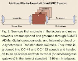
The first step in the transition to all-optical networking begins by reducing the cost of simple point-to-point transport. Costs are reduced by deploying ultra-long-reach transport (up to thousands of kilometers) that virtually eliminates electrical regeneration. Broadband services such as OC-3 (155.52 Mbits/sec), OC-12 (622 Mbits/sec), DS-x, and native data services that originate in the access and metro networks are still transported and groomed through SONET ADMs, digital crossconnects, and Internet protocol (IP) or Asynchronous Transfer Mode (ATM) switches. This traffic is groomed into OC-48 and OC-192 speeds and handed off to an all-optical network terminal (or access/egress gateway) in the form of standard 1310-nm interfaces (see Fig. 2). When ultra-long-reach transport is used in conjunction with next-generation electrical crossconnects at interconnection points, the following benefits are realized:
- Fast provisioning (even in point-to-point routes) since ultra-long reach is accomplished without regeneration
- Grooming of traffic before entry into the core network so that maximum bandwidth efficiency is enabled within the core
- Ability to handle local, regeneration, and next-generation crossconnect or SONET ADM traffic through the use of standardized interfaces at 2.5 Gbits/sec and 10 Gbits/sec
- Lower capital expenditures through the elimination of regenerators over ultra-long distances.
Despite these benefits, there are a number of penalties associated with deploying all-optical networks in only a point-to-point configuration. One is the inability to rapidly provision new circuits on an end-to-end basis because the crossconnects require physical termination of all circuits. The operational complexity and cost of physically terminating customer circuits at points of interconnection is another drawback--as is the potential for costly overlay builds of switching capacity.
The second step in the transition to an all-optical network is the addition of OADMs. OADMs serve the same purpose as their SONET ADM counterparts--the adding and dropping of optical channels. Performing this task in the optical domain eliminates the need for optical-electrical-optical (OEO) conversions in the electrical regenerators or crossconnects. Selected channels are dropped and/or inserted at various points in the network. The OADM transparency serves two functions. First, it eliminates OEO conversions, a primary contributor to network cost. Second, the OADMs serve as the basis for the transparent networking used in long-haul express circuits.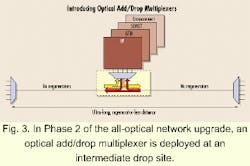
Figure 3 illustrates the introduction of an OADM at the intermediate drop site. Generally, more than 50% of customer circuits are express and do not need termination. In contrast, all circuits are terminated at the hub sites in traditional DWDM architectures because they do not have the optical reach. Phase 2 has the following attributes:
- Faster provisioning of express circuits is achieved because these circuits only require the addition of line cards at circuit endpoints
- Reduction in the number of transmitter/receiver line cards at intermediate nodes--resulting in a smaller footprint--since the express traffic is not electrically terminated and remains in the optical domain
- Substantial reduction in the size and cost of digital crossconnects because only local traffic (added, dropped, or regenerated) is terminated on the OADM.
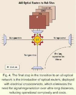
As with Phase 2, there is a substantial reduction in the number of regenerators and back-to-back terminals, saving enormous capital expenditure at degree-3 (or higher) interconnection sites. This equipment reduction lowers the operational complexity and costs associated with power, colocation, and basic maintenance. Because all express traffic can traverse a hub site in the optical domain, these circuits do not need to be electrically terminated at the hub, which further reduces the size and cost of the electrical crossconnect.
The phase 3 "full-mesh" network also supports differentiated services. The carrier can now provide both protected and unprotected services for mission critical, time-sensitive applications as well as "Web browsing" and consumer applications.
All-optical networks offer compelling business advantages, such as faster provisioning of customer circuits and operational simplicity, through optical transparency, the virtual elimination of regenerators, and the use of an end-to-end network provisioning and management system. These networks will feature new and more powerful equipment capable of supporting dramatic increases in the usable capacity of any fiber. This equipment includes amplifiers that support ultra-long distances, transparent OADMs, terabit-capacity routers, and very-high-density, open optical-network-access gateways. The maximum benefit is obtained when these network elements are used in combination with an all-optical network-management system.
When deployed with scalable capacity, all-optical networks will preserve capital investment and pre-empt frequent overbuilds.
David R. Huber is president and CEO of Corvis Corp. (Columbia, MD). In 1992, he founded Ciena Corp., before moving on to found Corvis in '97.