Harnessing the power of the optical Internet
Guru Parulkar, Growth Networks
As one of the fastest-growing segments of the communications market, the core routing market is projected to become a multibillion-dollar market in just a few years. The exponential growth in Internet bandwidth demand and optical bandwidth supply, due particularly to dense wavelength-division multiplexing (DWDM), has placed the core routing market in the midst of the biggest challenge faced by the builders of the Internet infrastructure-the delivery of high-speed applications to users. What has precipitated this crisis is the need to switch or route data between different optical fibers to reach applications.
Sophisticated switching or routing requires electronics. And while the capacity of optical fiber, number of users, types of applications, and per-application demand for bandwidth are all growing exponentially, the capacity and speed of electronic devices, which have grown per Moore's law, have not kept up with application demand and fiber capacity. Switching and routing systems used in the past can't scale to meet current and emerging requirements of the next-generation Internet. New approaches are required to handle the challenge of supporting hundreds or thousands of high-speed (OC-192) ports at a reasonable per-port cost.
At the heart of every switching and routing system is the switching fabric, which is responsible for the transparent interconnection of traffic between the input and output ports. This article examines evolving market requirements for core routers and the need for new switching fabric architectures within the core router.Once software-based, routing is now being handled in hardware. This shift has enabled system vendors over the last several years to achieve orders-of-magnitude increases in routing performance. However, these advances have fallen far short of meeting the Internet's growing bandwidth demand. Today's so-called terabit routers are really gigabit routers, and most solutions actually being deployed by carriers today are only in the 20- to 80-Gbit/sec nonblocking switching capacity range.
Thanks to DWDM, nearly infinite optical-fiber bandwidth has become available. The number of wavelengths carried per fiber is doubling every year, and the speed of each of these wavelengths is increasing from OC-12 (622 Mbits/sec) to OC-48 (2.5 Gbits/sec) and beyond; an abundance of bandwidth is suddenly available at the optical-fiber transport level. But while DWDM has led to optical-fiber bandwidth growth of over one million-fold in the 1990s, electronic bandwidth has grown just one hundred-fold during the same period. The result is a dramatic optical/ electronic bandwidth gap.
Internet demand is causing point-of-presence (PoP) bandwidth requirements to quintuple each year. In just three years, this equates to 125x bandwidth growth; by the year 2001, this puts Internet PoP bandwidth requirements at over 4 Tbits/sec. Switching fabric architecture is key to delivering scalable routing solutions to meet this capacity requirement. The alternatives for switching fabrics fall into two primary categories-single-stage fabrics and multistage fabrics.
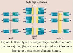
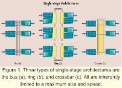
Today's core routers use single-stage switching fabrics, of which the four primary approaches are bus, ring, crossbar, and shared-memory architectures.Figure 2. In the Benes network illustrated (a), the overall switch has N inputs and outputs, and switch elements are organized into three columns. Note that the network structure results in N possible paths from each input to each output. The three-stage Clos network shown (b) is constructed from d by r switch elements in the input stage, N/d by N/d elements in the middle stage, and r by d elements in the output stage. Unlike Benes and Clos networks, the three-dimensional toroidal mesh (c) is constructed by interconnecting switch elements of fixed size. Switch elements are arranged into a 3-D mesh with wraparound. Each element is connected via unidirectional or bidirectional links to its six neighbors and has one bidirectional external link.
In a bus architecture, all ports share a single common bus. To achieve nonblocking operation, the bus must operate at N times the link speed (where N=number of ports). Input ports take turns writing cells onto the bus at the full bus rate, typically in round-robin fashion. For unicast traffic, each cell is addressed to one output port. Each output must be prepared to accept a cell on every cell cycle since every input may have a cell for the same output. (While such overloading of an output can arise in the short term, it will not persist in the long term.) The speed and size of a bus architecture is fundamentally limited by the technology for building a fast bus and driving it from N ports.
In a ring architecture, each port has an interface to a shared ring. The input ports write cells onto the ring, using a ring-contention scheme (e.g., token passing) to control access. Similar to a bus, each output must be prepared to accept a cell on every cell cycle, and the ring must operate at N times the link speed. However, since each ring interface is capable of regenerating the cell data, it is easier to support higher speeds. (Specifically, the capacitive loading effects on the shared bus are eliminated.)
A crossbar architecture can transfer multiple cells at once, with each transfer taking place at lower speed than in a bus or ring. A crossbar consists of a matrix of NxN crosspoints. When the crosspoint in position (x,y) is closed, a cell can be transferred from input x to output y. Typically, the transfer of cells to outputs takes place in cycles, where each output can accept one cell per cycle. A centralized scheduler is generally used to coordinate the transfers in each cycle, with the goal of maximizing the number of cells transferred without conflict. A redundant copy of the scheduler must be included, since it represents a single point of failure. To add to the challenge, the scheduling must take place at high speeds.
Optimal scheduling algorithms have complexity proportional to N3, which may be prohibitive at required speeds. Heuristics can be more efficient but require acceleration of the fabric to avoid excessive queuing at the inputs. (Typical acceleration is 2x to compensate for heuristic scheduling.) A crossbar architecture has queuing at the input and output ports of the switch fabric, with each queue dedicated to a particular port. Because each queue is dedicated and must be dimensioned to accommodate worst-case traffic, the total queue memory is large.
A shared-memory architecture reduces the total memory requirement by sharing a pool of buffers among input and output ports. Since memory is shared, the memory requirement is determined by worst-case total traffic. However, a shared-memory architecture requires a mechanism to transfer cells from inputs into memory and from memory to outputs. To maximize sharing, each memory location should be accessible at any time from any input or output. Typically, two crossbars are used: one between the input ports and the memory banks and one between the memory banks and the outputs. Thus, while a shared-memory architecture reduces the memory requirement of a crossbar, it requires twice the logic for moving cells in and out of memory.
Single-stage switching fabrics have two fundamental problems when larger systems are considered. First, while the cost per port is reasonable for small systems, it rises quickly as system size increases. Second, all single-stage switch fabrics are inherently limited by technology constraints to a maximum size and speed. Once these limits are reached, a single-stage solution offers no upgrade path for additional ports or increases in line speed. For these reasons, scalable switching systems must turn to multistage fabrics.
A multistage architecture is constructed by interconnecting multiple switch elements, each of which has a set of inputs and outputs and provides input/output connectivity similar to that of a switch. A switch element, however, has fewer inputs and outputs than the overall switch and thus can be constructed using a technology that does not scale. By interconnecting multiple smaller switch elements, a large and scalable switch can be constructed. Multistage architectures differ depending on how they interconnect the switch elements. Three approaches are considered here for multistage architectures-Benes, Clos, and three-dimensional toroidal mesh (3DTM).
A Benes network uses square switch elements (i.e. same number of inputs and outputs) interconnected over multiple stages. In general, a three-stage N part Benes network can be constructed from switch elements with N inputs and outputs and N switch elements per stage. This network structure results in N possible paths from each input to each output. The Benes output can be extended to any odd number of stages.
A Clos network generalizes the Benes network by allowing non-square switch elements. The interconnection of switch elements follows the same pattern as in the Benes network. In a three-stage Clos network constructed with d x r switch elements in the input stage, N/d by N/d switch elements in the middle stage, and r x d switch elements in the output stage, increasing r will increase the number of paths between any input and output and decrease the bandwidth required per path. However, the total bandwidth (and therefore, cost) of the network tends to remain about the same regardless of the choice of r. The Benes configuration-with r = N/d and thus square switch elements-is a convenient choice for implementation.
A 3DTM is constructed by interconnecting switch elements of fixed size (unlike Benes or Clos networks, where the switch element sizes can vary with N). The switch elements are arranged into a three-dimensional mesh with wraparound. Each switch element is connected via unidirectional or bidirectional links to its six neighbors and has one bidirectional external link. Routing requires independently traversing the necessary number of hops in each direction. The average number of hops to route in any direction grows as cube root of the number of ports; therefore, the total number of hops also grows as the cube root of the number of ports. To produce nonblocking operation, therefore, system cost is proportional to sub N4/3.
Though single-stage architectures have relatively simple designs and reasonable cost for small systems, they cannot meet the scalability demands of the next-generation Internet. Multistage architectures are more complex in operation, but they can scale to hundreds and thousands of ports-an absolute requirement for core routing systems of the next-generation Internet. Within multistage topologies, the Benes network architecture is the optimal choice because it offers the lowest complexity for scalable, high-performance systems.
Guru Parulkar, chief technology officer and co-founder of Growth Networks (Mountain View, CA), spent more than 11 years on the faculty of Washington University. He has chaired numerous professional programs and is an editor of the ACM/IEEE Transactions on Networking.
This article appeared in the February 2000 issue of Integrated Communications Design, Lightwave's sister publication.

