FBG dispersion compensation improves amplification designs and strategies
Lowering the cost of optical transport is a top priority for both system vendors and network operators in the telecommunication industry. The constant challenge to push costs lower is driven by the competitive nature of the industry but has, in recent years, been receiving increased attention in order to justify the intended/ongoing 10G to 40G transition of the industry.
In this article, we explain how fiber Bragg grating (FBG)-based chromatic dispersion compensation technology can facilitate these long sought-after cost savings by supporting new low-cost amplification strategies and new cost- and performance-optimized amplifier designs.
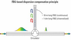
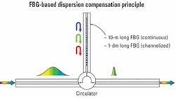
Chromatic dispersion compensation using reflective FBGs is fundamentally different from the incumbent technology used for dispersion compensation, dispersion-compensating fiber (DCF). Dispersion management utilizing FBGs is based on the introduction of wavelength-specific time delays through the use of a precisely chirped fiber grating. The grating can be made to mimic the dispersion characteristics of the fiber or span intended for compensation (see Fig. 1).
The FBG approach to dispersion compensation clearly provides several advantages over utilizing spools of DCF. However, this article will mainly focus on the unique properties directly enabling novel and cost-effective amplifier architectures and designs.
The most obvious and commonly known advantage related to FBG-based dispersion compensation modules (FBG-DCMs) is low insertion loss (IL). Typically, a 120-km FBG-DCM has an insertion loss in the range of 3 to 4 dB depending on type, while a DCF equivalent suffers IL of approximately 10 dB or even greater. Furthermore, the FBG-DCM has an advantage in having virtually constant IL versus span length whereas the IL of the DCF-DCM grows linearly with span length.
Apart from the favorable form factor, this length difference also yields one other key advantage of the FBG-DCM compared to the DCF-DCM, namely low latency. The latency, defined as the time delay of an optical signal imposed by any in-line device, is in the case of passive dispersion compensation directly proportional to the optical path length of the device.
Latency numbers in the range of 100 µsec are not uncommon for DCF-DCMs. On the other hand, the latency of a FBG-DCM is typically three orders of magnitude smaller and can in most practical cases be considered negligible.
The ability to tolerate high optical powers without suffering from penalties caused by nonlinear effects is also one prominent characteristic separating the FBG-DCM from the DCF-DCM. Although a DCF will display nonlinearity effects at rather low optical powers, typically limiting the power to -2 dBm per channel, the FBG-DCM will not introduce such effects even at the highest power levels present throughout any traditional optical network.
The favorable performances regarding insertion loss, latency, and the lack of nonlinear effects at high optical power in combination with a significantly smaller form factor are all key properties, not only allowing for cost-efficient amplifier designs but also providing substantial cost savings in general.
Conventional EDFAs can be optimized in a number of ways if the unique qualities of the FBG-DCM are properly leveraged. Significant improvements can be achieved not only regarding performance, such as improving noise figure (NF), but also in size, cost, and robustness of design
Let us start by examining what degrees of freedom are offered by the low and virtually span-length-independent loss offered by a FBG-DCM.
A traditional mid-stage access amplifier (MSA) is typically designed for a mid-stage DCF loss of about 10 dB. Worth noticing, though, is that in reality the actual loss between preamplifier and booster can be as high as 12 dB, since optical isolators are needed to prevent backscattering. The 10-dB loss permitted at the mid-stage is able to support approximately 100 to 120 km of DCF-based singlemode fiber dispersion compensation.
The same IL limit yields a dispersion compensation length of approximately 400 km for a continuous FBG-DCM and significantly longer for a channelized version. The fact that the FBG-DCM incorporates circulator(s) by default further facilitates the exclusion of the loss-prone optical isolators in the amplifier mid-stage block.
The low IL of the FBG-DCM may be valued differently depending on network topology, individual link design, and tolerance. Low IL can be used to simplify the MSA design, but in some cases where in-line dispersion compensation is sufficient, it may even lead to the removal of the MSA altogether. In the latter case, the direct cost savings on amplification would amount to approximately 40% per span.
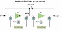
A traditional MSA (Fig. 2) is designed to mitigate the high IL of a DCF-DCM by, for instance, utilizing a triple-stage, dual-pump approach (i.e., a dual-stage preamplifier in combination with a booster).
The main elements of this design are a dual-stage variable-gain preamplifier and an additional variable optical attenuator (eVOA) placed before the mid-stage access. The variable-gain preamplifier, which includes an eVOA between the two sub-stages, provides for the variable gain operation of the entire MSA (i.e., flat gain over the entire operating gain range). The additional eVOA before the mid-stage access is required to support different DCF losses for different span lengths.
In principle, the two eVOAs could be combined into one, leading to a much simplified design. However, in such a design the gain of the preamplifier would have to be substantially reduced to avoid high output power at the output of the preamplifier (i.e., very high pump power requirements). This, combined with the high mid-stage loss, would lead to drastically reduced NF performance of the MSA as a whole.
However, even with the dual-stage design of the preamplifier, the NF performance of the MSA is limited by another factor: To minimize nonlinear effects associated with the DCF, the input power to the DCF is usually limited to about -2 dBm per channel. This again limits the gain of the preamplifier, which adversely affects the NF performance.
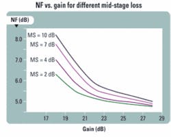
By simply replacing a DCF-DCM with an equivalent FBG-DCM, the low and virtually span-length-independent IL at mid-stage means that the amplifier does not have to be designed with the aforementioned limitations in mind. The low mid-stage loss allows the two eVOAs to be combined without adversely affecting the overall NF performance. In addition, the simplified design requires fewer passive components (e.g., isolators, pump signal combiner, taps), further improving the NF performance. Finally, the fact that the input power to the mid-stage is not limited by nonlinear effects allows further improvement of the NF. The overall improvement in NF performance due to the reduced mid-stage loss is illustrated in Fig. 3 for a typical MSA with a variable gain range of 18 to 28 dB.
Furthermore, the lower mid-stage loss as well as the lower overall loss associated with the simplified design means that less total pump power is required. The lower pump power requirement opens up the possibility of using a single optical pump to serve the entire MSA. However, in order to be able to use a single optical pump approach additional requirements are necessary, which brings us to the issue of mid-stage access latency and transient suppression.
Transients are a reality in all optical networks. They occur due to normal network operation such as adding and dropping channels, as well as unintentional fiber breaks and network rerouting and reconfiguration. Transients need to be properly managed to avoid strong bit-error-rate (BER) bursts and even damage to receivers.
Normally, these transients have rise and fall times in the microsecond range, which is on the order of and often below the actual latency imposed by a standard DCF-DCM. Thus, to minimize the effect of the transient, it is necessary for each amplifier stage to independently respond to the transient as it enters the stage, requiring separate, independent pumps and control loops for each stage.
In the case of the FBG-DCM the latency is virtually nonexistent for all compensating values used in optical transport links. This unique asset provides the MSA designers with the opportunity to use a single control loop and hence a single pump to control the entire amplifier.
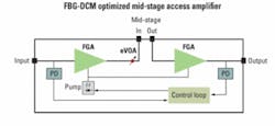
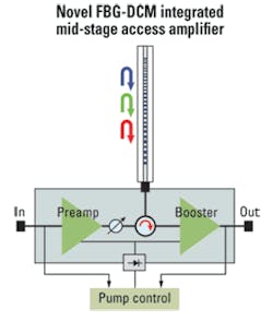
Taking into account all of these considerations, Fig. 4 shows an MSA design optimized for FBG-based dispersion management. This design has the advantage of much reduced component count (single pump, single eVOA, fewer detectors, fewer passive components), as well as significantly simplified electronics (single control loop instead of two separate control loops). This results in up to 30% cost reduction, as well as 50% footprint reduction compared to the conventional MSA design. Even further cost reduction can be achieved by integrating the circulator from the FBG-DCM within the amplifier, as shown in Fig. 5.
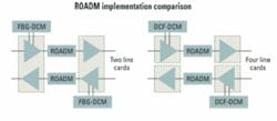
The reduction in footprint can also be translated into significant system cost savings by integrating more components on a single line card. For example, the MSA and FBG-DCM may be integrated on the same line card or two amplifiers can be integrated in the same package and mounted on a single line card. This can be particularly useful in ROADM systems requiring east/west separation of amplifier stages.
For example, Fig. 6 shows a typical ROADM implementation using FBG-DCM on the one hand and DCF-DCM on the other. As can be seen, the FBG-DCM implementation requires only two line cards for the amplifiers, whereas the DCF-DCM implementation requires four line cards.
By utilizing FBG-based dispersion compensation there are a number of ways to facilitate cost-effective optical transport apart from the previously discussed FBG-DCM optimized MSA. The cost savings that can be achieved are closely related to the specific topology of a given optical transport link, but some simple and straightforward examples immediately stand out.
Drawing on the low IL, the equivalent of hundreds of kilometers of singlemode fiber dispersion compensation can be concentrated in single nodes to enable cost-effective point-to-point networks.
The low loss and high power tolerance further provide the network designer with the possibility of placing the compensation either directly after the multiplexer on the transmitter side or after the booster. In the case of DCF-DCM, issues normally arise either from high loss limiting the amount of dispersion compensation close to the transmitter or the introduction of high nonlinearity penalties if placed directly after the booster.
Networks requiring distributed dispersion compensation, typically an architecture used when signal fidelity at each node is vital, normally rely on the use of MSAs or node-specific DCMs. As mentioned before, the elimination of MSAs is, in some networks, an attractive strategy to pursue. If such a strategy is fully implemented in a network the amplifier-related cost savings per span can be as high as 40%.
Even in networks where MSAs are not used the IL-related cost savings could still be significant. By simply utilizing amplifiers with less available output power the savings on amplifications can be in the area of 20% for a standard 80-km span.
FBG-based chromatic dispersion management provides the telecommunications industry with unparalleled possibilities when in comes to network cost and performance optimization. The increased focus on cost, especially considering the future of 40 and 100G networks, is effectively addressed by this unique and in many aspects disruptive technology -- a conclusion supported by the thousands of units currently deployed in various networks worldwide.
Fredrik Sjostrom is responsible for technical sales and Bengt Johansson is CTO at Proximion Fiber System AB. David Menashe, PhD, is vice president and chief scientist at RED-C Optical Networks.
