Raman amplification extends CWDM's reach
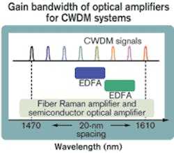
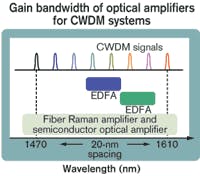
Figure 1 illustrates the gain bandwidth of various optical amplifiers that might be used for CWDM systems. EDFAs are common elements in optical networks; however, their gain bandwidth does not match well with the channel spacing typical of CWDM equipment. Semiconductor optical amplifiers (SOAs) can cover the wide gain band but have inherent technical limitations. On the other hand, fiber Raman amplifiers (RAs) can extend the usable optical bandwidth by optimizing the pumping lightwave spectrum to meet CWDM requirements.
The effectiveness of a lumped (discrete) Raman amplifier (LRA) within a CWDM system depends on the gain flatness, which is due to the optimization of the wavelength allocation and the pump conversion efficiency. By employing pumping lasers at two wavelengths, gain flatness of <1.5 dB at the center wavelength of CWDM signals can be achieved. But to achieve effective Raman amplification with conventional pumping lasers, highly nonlinear fibers (HNLFs) with a high Raman gain coefficient are used in the LRAs. The Raman gain coefficient of HNLF is twice that of conventional dispersion compensating fiber.
Table 1 displays the characteristics of the amplifiers that can be used as a booster amplifier for CWDM systems. The multiplexing/demultiplexing filter for a CWDM system typically has a full width at half-maximum (FWDM) of 13 nm. Because the CWDM signals are essentially affected by the beat noise between signals and amplified spontaneous emission noise of the amplifier, booster amplifiers generally are necessary for CWDM systems.As Table 1 shows, an LRA is a good choice for a booster amplifier in CWDM systems. The LRA provides both the seamless wideband amplification that an EDFA cannot as well as the good transmission characteristics the SOA lacks.
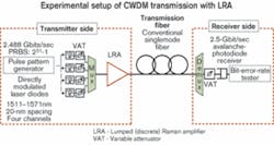
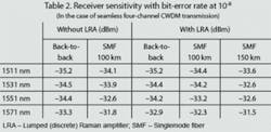
Figure 2 illustrates an experimental setup of CWDM transmission with a booster LRA. The wavelengths of four-channel CWDM signals from multi-quantum well (MQW) DMLs were arranged from 1511 to 1571 nm with 20-nm spacing. The bit rate of each CWDM signal was 2.488 Gbits/sec (OC-48). The input and output power of the LRA was +0 dBm/channel and +10 dBm/channel (a total of 16 dBm), respectively. The net gain of each channel was more than 10 dB, with a maximum noise figure of 6.5 dB. The polarization-dependent gain of the LRA was <0.3 dB.The cost of the LRA is comparable to that of a four-channel CWDM repeater. Taking both capital and operational expenses for constructing and maintaining additional repeater sites into consideration, CWDM systems employing LRAs are clearly more economical. The use of LRAs in CWDM systems should expand the application of CWDM into fields where DWDM systems employing EDFAs are commonly used today. The advent of the LRA should help increase the market for CWDM systems in the future.
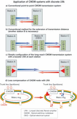
Reach extension of CWDM systems using LRAs allows a flexible operational arrangement of the CWDM approach with low operating expenses without building repeater stations. LRAs are optimized for CWDM applications with the characteristics of seamless amplification and saturation output power that could not be achieved by employing EDFAs or SOAs. By using a booster LRA, 150-km transmission with conventional SMF has successfully been demonstrated. Moreover, not only is transmission length enhanced, but also the loss compensation of OADMs, and flexible telecommunications systems can be achieved by employing CWDM systems with LRAs.
This work is supported in part by National Institute of Information and Communications Technology (NICT).Toshiyuki Miyamoto is a research engineer in optical communications for the Optical Communications R&D division of Sumitomo Electric Industries (Yokohama, Japan).Ron Lindsayis a director of engineering at ExceLight Communications (Durham, NC). They can be reached at [email protected] and [email protected].
