Cable guidelines for customer premises

Cable guidelines for customer premises
Detailed analyses of singlemode and multimode fiber characteristics and costs help ensure a superior network installation
PAUL KOLESAR
AT&T NETWORK CABLE SYSTEMS
Increasing bandwidth demands of users and the evolution of higher bandwidth applications during the last decade have made fiber the media of choice within the backbone segments of the premises network. Today, most fiber installations within customer premises consist of multimode media, but the bandwidth constraints of multimode media may limit the ability of the network to provide future broadband services.
The proposed Telecommunications Industry Association/Electronic Industries Association 568-A commercial building telecommunications cabling standard recommends 62.5/125-micron graded-index multimode fiber for customer premises installations because it is the standard fiber used for almost all fiber-based local area network applications. This popularity results from its versatile design that balances loss, bandwidth, coupling efficiency (light gathering capability) and operation in both short- and long-wavelength operating windows approaching 850 and 1300 nanometers.
Loss (attenuation), which diminishes the signal power, and dispersion, which reduces the bandwidth (information capacity), can limit the operating distance of fiber systems. The total loss accumulates from the cables, connectors and splices used in a network link. Bandwidth is affected by the optical transmitter and fiber. For systems operating at greater than 100 megabits per second, bandwidth almost always becomes more restrictive than loss.
The fiber bandwidth specification is known as the modal bandwidth-distance product, which equals the modal bandwidth of a fiber times its length. However, the modal bandwidth-distance product only specifies part of the bandwidth criteria of the media, because the bandwidth of multimode optical fiber is limited by both modal and chromatic dispersion. Both types of dispersion cause the light pulses to widen as they travel down the fiber, blurring the distinction between adjacent pulses and degrading the bit-error-rate performance of the link.
Modal dispersion is caused by the path length difference of each optical mode, which results in different propagation times. Standard 62.5/125-micron multimode fiber has a minimum modal bandwidth-distance product of 160 megahertz/kilometer at 850 nm, and 500 MHz-km at 1300 nm.
Chromatic dispersion is caused by the speed difference of each wavelength and is a function of both the fiber material and the chromatic content (center wavelength and spectral width) of the transmitter. Consequently, systems that use transmitters with wide spectral widths will suffer from higher chromatic dispersion (and lower chromatic bandwidth) than those using narrow spectral width transmitters. Also, for a given spectral width, glass fiber produces much less chromatic dispersion near 1300 nm than it does near 850 nm.
The bandwidth-distance product rating of a fiber only indicates the effects of modal dispersion because it is measured using narrow spectral width laser transmitters. If the fiber is used to support wide spectral width transmitters, such as light-emitting diodes, then chromatic dispersion can become the dominant bandwidth-limiting effect.
The transmitter also contributes to the system`s bandwidth by its transition time. The transmitter bandwidth depends on how fast it can turn on and off. The fiber system`s bandwidth at the exit end of the fiber (just before the receiver) is known as the exit bandwidth, which is a combination of the fiber and transmitter bandwidths. The lowest acceptable exit bandwidth is determined by the receiver and is sometimes defined in terms of maximum fiber exit transition time.
The following rules can be used to help categorize fiber-optic systems according to their transmitter type, baud rate and fiber type:
Fiber LANs operating at less than 50 Mbaud generally use 850-nm LEDs on multimode fiber. However, these devices are available for applications to 155 Mbaud.
Fiber LANs operating between 50 and 250 Mbaud generally use 1300-nm LEDs on multimode fiber. Recently, these devices have been proposed for 622-Mbaud applications.
Systems operating at greater than 250 Mbaud generally use 1300-nm lasers on singlemode fiber.
Recently, 780-nm lasers, developed for compact disk players, are making inroads into all baud-rate applications on both media types.
Plotted operational data curves provide a way to approximate if a TIA/EIA-568-A compliant multimode fiber-optic installation will provide sufficient bandwidth to support an application. These curves apply to the most common systems that use ordinary digital signaling, on a single optical carrier, without wavelength division multiplexing. The transmitter is assumed to excite all optical modes. For example, assume that the transmitter transition-time bandwidth occupies 70% of the operating baud rate. The curves would represent the distance at which the exit bandwidth is reduced to 50% of the operating baud rate. Because of these assumptions, the curves are only approximations.
Three solutions can be used if a system is bandwidth-limited: Insert multimode repeaters along the link at separations less than the bandwidth-limited distance, use higher performance transmitter technology (for example, long instead of short wavelength, or lasers instead of LEDs) on multimode fiber, or use singlemode fiber and transmitters.
For most LAN applications, a station or hub inherently acts as a repeater. Some LANs offer a choice of media and transmitter technologies. Multimode-to-singlemode converters may be available for other applications.
The 8- to 10-micron core of conventional singlemode fiber propagates only one mode of light and therefore does not suffer from modal dispersion. The bandwidth of singlemode fiber is primarily limited by chromatic dispersion. The exit bandwidth of a singlemode system is almost completely controlled by the transmitter`s chromatic content and transition-time bandwidth. Using 1300-nm lasers, typical singlemode systems achieve 20 GHz-km bandwidth performance.
Singlemode fiber transmission depends on the operating wavelength. Conventional singlemode fiber supports only one transmission mode when operated at wavelengths longer than 1250 nm. Conventional singlemode fiber is actually step-index multimode fiber for 780- and 850-nm applications. Consequently, singlemode fiber bandwidth is greatly reduced by both modal and chromatic dispersion when the transmitted signals operate at short wavelengths.
Several applications for singlemode fiber in private networks include:
Telephony multiplexers--Services from the telephone company delivered at DS-1 (1.5 Mbits/sec) to DS-3 (45 Mbits/sec) or OC-1 (52 Mbits/sec) to OC-12 (622 Mbits/sec) rates using 780-, 1300- or 1550-nm lasers usually on singlemode fiber.
Broadband analog video--Cable-TV delivery using analog modulation of 1300-nm lasers operating at approximately 600 MH¥over singlemode fiber.
Fiber distributed data interface--A 125-Mbaud token-passing ring LAN standard capable of operating on multimode fiber using 1300-nm LED transmitters, or on singlemode fiber using 1300-nm lasers.
Fibre Channel--An emerging standard for the interconnection of computers and peripherals at rates of 132.8, 265.6, 531.3 and 1,062.5 Mbaud. It uses 1300-nm LED transmitters on multimode fiber at the two lower rates, 780-nm lasers on multimode fiber at the three upper rates, and 1300-nm lasers on singlemode fiber at the three upper rates.
Proprietary computer links--Systems to interconnect computers and peripherals using fiber. One popular system operates at 200 Mbaud using 1300-nm LEDs on multimode and 1300-nm lasers on singlemode fiber.
High-performance parallel interface--An ad-hoc specification defining the serialization of the Hippi standard used on supercomputers. It operates at 1200 Mbaud using 1300-nm lasers on singlemode fiber.
Multimode-to-singlemode converters
Multimode-to-singlemode converters have two basic applications. The first application provides singlemode capability for equipment that is only available with multimode interfaces. If the option to use available multimode repeaters is unacceptable, singlemode fiber may be used by inserting a multimode-to-singlemode converter in the link. In the second application, singlemode equipment may be available, but multimode equipment may already be installed. In this case, adding a multimode-to-singlemode converter may be less expensive than replacing the existing equipment.
Multimode-to-singlemode converters are generally inserted in the link that is downstream from the multimode transmitter, but may be remotely located as long as the power budget and bandwidth requirement are not exceeded. The converter receives the multimode signal and drives a transmitter capable of launching an optical signal into singlemode fiber.
Converters are available in two basic types: multiprotocol and single protocol. Multiprotocol converters are designed to handle a variety of protocols used by the more common LANs such as 10Base-F, token ring and FDDI. Multiprotocol converters do not retime the signal, and therefore cannot reduce timing jitter. The output merely follows the input signal. On the other hand, single protocol multimode-to-singlemode converters are tailored to only one type of LAN. They often have more functions, such as signal retiming, and generally operate in only one wavelength region.
Multiprotocol converters are available with both short- and long-wavelength input and output. Because the input and output wavelengths may be different, they can convert a short wavelength system to long wavelength for operation on singlemode fiber, and then back to short wavelength at the other end of the link.
Mixed media installations
Placement of multimode and singlemode fiber in the backbone, especially in segments that are difficult or expensive to retrofit with singlemode later, is important. Plotted 1300-nm laser curve rate reveals the following basic guideline: Singlemode fiber should be installed whenever the expected baud rate (in Mbaud) times the span length (in kilometers) between endpoints approaches or exceeds 500.
But, why worry about when to install singlemode? Why not install it everywhere and forget about multimode? Cost is the reason. Multimode systems cost much less than singlemode systems. The manufacturers of opto-electronic equipment utilize LED and short wavelength laser transmitters whenever possible because they are much less expensive than 1300-nm laser transmitters. The larger core size of multimode fiber allows looser tolerances on splice, connector and opto-electronic components, resulting in higher yields and lower costs.
Once the need to install singlemode has been identified, such issues as the number of fibers, the type of cable, cable management, administration, recordkeeping and the use of different connectors and splices need to be addressed.
The number of strands of both multimode and singlemode fibers that should be installed in a backbone segment depends on the present and future applications that must be simultaneously supported by that segment. To determine the amount of fiber to install, take into account the type and number of fibers that each service requires and the number of services that will share the backbone segment. Add up all of the required fibers and add in at least 50% spare capacity of dark fibers to arrive at the minimum suggested fiber count. Increasing the spare fiber count above 50% will further future proof the installation.
Choose a cable design appropriate for the type of installation and run separate cables for multimode and singlemode fibers. Hybrid cable with both multimode and singlemode fibers in one sheath are not recommended. Initially, these cable types may appear attractive. However, in practice, hybrid cable can prove problematic because of the lack of availability and higher cost. Furthermore, difficult fiber-type identification might lead to inappropriate use of splice and connector hardware and unintended interconnection of multimode to singlemode fibers at splice points. Using separate cables helps to identify and segregate the two fiber types, reducing confusion during installation, maintenance and administration.
To improve the management of the fiber system for administration and recordkeeping, route the two fiber types to separate patch panels. The fiber type should be identified by distinctive labeling. Color coding the connectors and couplings (adapters) is recommended. The use of blue for singlemode and beige for multimode connections is consistent with the emerging TIA/EIA-568-A.
Additional color coding on the patch panel is recommended to identify the position of the cable segment within the distribution system hierarchy established by TIA/EIA-568. Color coding labels with instructions are available to create patch panels compliant with TIA/EIA-606 administration standard for the telecommunications infrastructure of commercial buildings.
Up-to-date records of the distribution system are essential for efficient usage of the network. Installation should follow all the labeling and recordkeeping practices of TIA/EIA-606. q
Paul Kolesar is a member of the technical staff at AT&T Network Cable Systems in Middletown, NJ.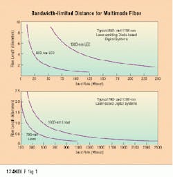
The graphs provide a way to approximate if an EIA/TIA-568-A compliant multimode fiber-optic installation will provide sufficient bandwidth to support an application. These curves apply to the most common systems, which use ordinary digital signaling, on a single optical carrier, without wavelength division multiplexing. The transmitter is assumed to excite all optical modes, and the transmitter transition-time bandwidth is assumed to be 70% of the operating baud rate. The curves represent the distance at which the exit bandwidth is reduced to 50% of the operating baud rate.