Increasing fiber in cable's diet
FTTH is usually associated with telco networks. But greenfield FTTH deployments can complement an MSO's existing hybrid fiber/coax infrastructure as well.
By Jim Farmer
Wave7 Optics
Cable-TV companies have long employed fiber optics to transport signals most of the way to the subscriber. Over the past two decades, they have pushed fiber closer and closer to the customer for several reasons.
While most of the fiber-to-the-home (FTTH) buzz has surrounded the telephone industry, which is arguably leading in FTTH deployment at this time, the cable-TV industry is starting to deploy this technology too, primarily in greenfield applications where new infrastructure must be installed anyway. This paper highlights how easy it is for cable-TV companies that employ hybrid fiber/coax (HFC) networks to deploy FTTH in greenfield situations while maintaining their existing HFC networks until end-of-life.
Comparing HFC with FTTH
The cable-TV industry's hybrid fiber-coax (HFC) network is better able to deliver modern telecommunications services than is the telephone industry's century-old twisted-pair network. Thus, cable-TV companies generally don't feel the same upgrade pressure as does the telephone industry. FTTH, though, is as much of an improvement over HFC as HFC is over twisted pair. Thus, the pressure is starting to mount as Verizon, a number of independent telephone companies, and many electric utilities get into the FTTH business.
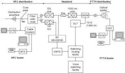
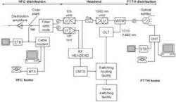
Figure 1 shows an example network, with a headend in the center that supplies the triple-play video, voice, and data services to both HFC distribution (left) and FTTH distribution (right). A home taking triple play services is shown under each distribution network. Both HFC and FTTH networks can use the same headend pieces.
For HFC, all traffic must be modulated onto RF carriers in order to be transported on the HFC network. The FTTH network can transport the same downstream (DS) RF signals. Some of those RF signals transport data (including voice) traffic, which is transported separately, on different wavelengths, in the FTTH network. This would free up one or more RF channels for video on the FTTH side, but since the RF channels are tied up transporting data on the HFC side, they likely would not be used for video on the FTTH side, at least not in the early days.
Data (including voice) traffic is routed to the cable modem termination system (CMTS) for the HFC side, and to the optical line terminal (OLT) on the FTTH side. The OLT is the network-side data interface to the FTTH system. Data is transmitted downstream at 1490 nm and upstream at 1310 nm. For the HFC network, it is transported downstream on the downstream optical transmitter (DS xmtr) and the downstream optical fiber. All signals, data and video, travel downstream on the HFC side over a single wavelength on a dedicated fiber-optic strand to the fiber optic node. Here they are turned into RF signals for transport over the coax portion of the network. Upstream signals arrive at the fiber-optic node on lower-frequency RF carriers (frequency division is used in the coax portion to separate the two directions). At the node they are converted to light, which is transported to the headend on a separate fiber.
In the FTTH portion, the downstream RF signals are supplied to a 1550-nm optical transmitter and are wavelength-division multiplexed with the 1310/1490-nm data optical signals. All are transported on a single fiber strand to a group of subscribers. In some cases, this same 1550-nm RF transmitter may be used for the HFC plant.
For the HFC plant entering the home, video signals are already in a format to be supplied directly to a set-top box (STB) or, in the case of analog video and a limited number of digital video cases, directly to a TV. Data is demodulated in the cable modem. An output of the cable modem is usually a 10/100Base-T Ethernet interface to a computer or to a home network. A second Ethernet connection may be used for the telephone adaptor, known as a media terminal adaptor (MTA). In many cases, the MTA is embedded in the cable modem, in which case it is called an embedded MTA (EMTA).
Compare this HFC home with the FTTH home on the right side of the figure. An optical network termination (ONT) terminates the fiber at the home. Typically the ONT is mounted on the outside of the home. This is desirable to let the system operator have access to his device at all times. The ONT has an RF interface for the RF video, which is shown feeding an STB, then a TV. Again, analog service may be supplied directly to the TV without use of an STB; where CableCards are used, digital signals may be supplied directly to TVs.
Note that there is no need for a cable modem, as the ONT includes one or more Ethernet connections directly. Also, the functionality of the MTA is usually built into the ONT, eliminating the need for that device. Thus, with the exception of the STB, all of the operator's equipment is located on the outside of the home. Furthermore, the ONT is a managed element in the network, making it possible in many cases to solve problems without ever having to roll a truck to the home.
A nice feature of the ONT is that it can contain service disconnect switching. For example, if a subscriber moves, all services can be cut off without having to send someone to the home. When someone new moves in, service may be restored from the office. If a subscriber doesn't pay his video bill, video service can be cut off without affecting data or voice. The same cannot be said for HFC.
Additional considerations
Besides the efficiencies of having almost all equipment on the outside of the home, there are other advantages of the FTTH system. The HFC system has active electronics in the plant; the fiber-optic node and multiple distribution amplifiers are distributed throughout the network. These must be powered. Field-mounted electronics offer points of failure that simply don't exist with the passive FTTH plant. Also, the coax portion is subject to mechanical issues related to the large, stiff medium (hardline coax), whereas the fiber medium is small and flexible. Furthermore, electrical problems exist within the coax plant that are not there with the FTTH plant. These include sheath current, which can damage equipment during power surges or lightning strikes. It also includes RF leakage, which in the HFC plant requires cumbersome and expensive composite leakage index (CLI) measurements not required in FTTH.
In minimizing the impact of adding FTTH to an HFC plant, it is necessary to make the data and voice protocols as alike as can be. Data protocols are based on Ethernet and Internet Protocol in both HFC and FTTH, so this is not an issue. Voice over Internet Protocol (VoIP) is compatible, too. The cable industry early on standardized on the NCS protocol, which is a profile of the standard Media Gateway Controller Protocol (MGCP) protocol used first in FTTH systems. It is easy to build ONTs that are compatible with both MGCP and NCS. Recently both HFC operators and FTTH operators have become interested in supporting Session Initiation Protocol (SIP), a very versatile protocol that does more than just voice. The same SIP-based voice switching facility can operate with both HFC and FTTH.
We failed to mention the small box labeled "Pre" at the input to the 1550-nm optical transmitter. This is a pre-emphasis network that is sometimes used to boost the amplitude of the lower RF channels with respect to the higher channels. The reason for doing this is to compensate for interference generated as a result of stimulated Raman scattering (SRS) in the optical fiber. SRS causes crosstalk between the downstream data at 1490 nm and the RF signals on 1550 nm. The result in some cases can be reduced carrier-to-noise ratio (C/N) in the lower RF channels, causing snow in the pictures. The most severe effect of SRS, however, is caused by idle codes sent when no data is available to transmit. This idle condition can produce strong interference in certain channels. The effect can be mitigated by applying certain patent-pending techniques to the data carrier.
It is easy to add FTTH to an existing HFC system. The HFC CMTS is not needed, but an OLT is added at the headend. Data is compatible between the systems. The same voice system serving the HFC plant can serve the FTTH plant, as can the same video system. We expect HFC operators to continue operating their good HFC plant for several more years, but they are starting to migrate now to FTTH for new builds. The costs are competitive and the benefits are substantial.
James O. "Jim" Farmeris chief technical officer at Wave7 Optics. He can be reached at [email protected].

