HFC upgrades: the next logical step
HFC upgrades: the next logical step
An architecture called "fiber to the power supply serving area" may hold the key to legacy HFC upgrades.
By DONald T. GALL and MITCH SHAPIRO
In our last two columns, we have looked at a "fiber-to-the-passive coaxial" (FTPC) network architecture that is well suited to greenfield applications. This type of architecture has many advantages, both technically and operationally, over so-called traditional hybrid fiber/coaxial-cable (HFC) networks for new builds but is difficult to justify for operators with legacy networks.
HFC architectures were adopted by the cable industry as the best balance between capitalizing on their existing coaxial network and the cost of installing a fiber-optic overlay. The size of the node in most cases was determined by calculating future network demand for data applications. Since the coaxial network is capable of supporting a relatively high network capacity, the node service area was set typically between 500 and 2000 homes passed.
What was not considered by many in the industry, however, is the operating requirements necessary to run a truly functional bidirectional network. By activating the return, you effectively double the complexity of the network. Since the return portion of the network operates in a different frequency range (typically 5 to 40 MHz) and every customer premises is a transmitting point in a large parallel bus, the technical skills necessary to maintain the upstream plant are somewhat different than in the downstream plant. This difference has major ramifications throughout the cable industry as companies begin activating digitally modulated two-way services.
It can be argued that a well-maintained plant and correctly trained personnel can overcome any operational issues. In reality, however, this is often not the case. In many situations, the resources and training necessary to operate two-way plant are either inadequate or nonexistent. Since the cable industry already has a dubious reputation for customer service, delivering poor service in these new businesses would not be a wise move.
In an HFC network, the coaxial portion operates as a large electronic bus. The larger the bus is, the more complicated it is to operate. An HFC network that has been designed to pass 500 homes has 500 potential sources for data signals and system impairments, as well as an average of 35 amplifiers and two power supplies feeding back to one location. Obviously, a node to accommodate 2000 homes passed will have four times the equipment and sources. The problem is the operational requirements do not scale the same way--system fault tolerances become smaller and the time to repair can be considerably longer.
In other words, the smaller the "coaxial bus," the better. The trick is to find a happy medium that allows legacy systems to support future business plans without spending unnecessary capital up front. In the last few years, the cost of both the fiber-optic cable and electronics have continued to trend down, which has allowed some very cost-effective designs using smaller nodes.
Design goals include network reliability, simpler return solutions and, in some scenarios, savings in fiber electronics and consumer terminals. The problem in implementing almost any engineering project is that there are always cost considerations. An elegant engineering solution that doesn`t have a real-world payback will interest only government agencies. It does not make sense to force a solution that yields a very small improvement at a cost of several thousand dollars per mile.
In a typical plant, the costs of building new fiber and coaxial plants are close to equal. In upgrade situations, however, the equation is not that simple, since any fiber installed is added in parallel to the existing coaxial distribution plant, escalating the cost per mile.
There is a point at which the benefits of fiber have a diminishing impact on network reliability and flexibility. As relative equipment costs change, so too does the optimum crossover point between fiber and coaxial plants. Tracking this "crossover point" is not a trivial task, since network designs vary widely in density and connectivity. Most benchmark designs use 95 to 100 homes per mile, since this is the overall average of plant across the United States. Although these designs will work well for the "average" network, designing in rural or very urban environments may require a different strategy.
FPSA in HFC upgrade
A "fiber-to-the-power supply serving area" (FPSA) design can be viewed as the next logical step in HFC upgrade design. It comes closer to the reliability of an FTPC network, lowers the overall number of active devices, and has several options for graceful upgrades. It is being used by Time Warner in some networks, and a variation of it is under consideration by MediaOne. The design trades off the cost of more fiber and fiber electronics for fewer coaxial amplifiers and power supplies per mile of plant. Its cost is comparable to standard HFC designs in plant densities above 65 homes passed per mile, as long as the existing coaxial trunk is less than 50% underground. This is a very rough rule of thumb because of variations in regional labor costs.
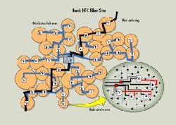
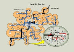
Discussion of FPSA should begin with a basic HFC building block: a fiber star that has a service area of approximately 20,000 to 40,000 homes passed (see Fig. 1). This service area will ideally have a distribution hub placed near the center of the star. The hub is connected to the rest of the plant by a fiber ring. This configuration limits the exposure to an extended outage from a fiber cut to between 10,000 and 20,000 homes passed. It also holds fiber cable bundle sizes down to reasonable levels. Fiber loss budgets, less splits, are typically less than 4 dBc.
In this design, four to six fiber-optic cables are deployed to each group of 500 homes. Two of the fibers are used for forward distribution and two are used in the reverse. The remaining fiber count is used for spares and/or future growth. Each of the "forward" fibers is field-split to supply fiber inputs to an existing trunk location corresponding to the center of a power supply area. Depending on density, the average is from a two to four split. Most of the upgrade designs to 860 or 750 MHz and 500 homes per node average about 2.5 power supplies. The FPSA design has only one power location per area, improving overall reliability, and makes troubleshooting relatively easy.
In the typical fiber star, the fiber losses are from 2 to 4 dBc at 1310 nm. This amount allows approximately 10 dBc of split loss for a laser with a 13-dBc budget at 51-dB carrier to noise, allowing service to an average of eight nodes per transmitter.
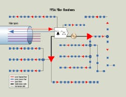
The fiber receivers are placed to take advantage of the higher output levels that can be used with a maximum cascade of one bridger and three line extenders in cascade (see Fig. 2), in most instances, an existing bridger location in a 270- or 300-MHz plant design. The receiver should support two outputs with a minimum output level of 44 to 46 dB and two additional outputs of 48 dBmV at the highest design frequency. Analog distortions should be -64 dBmV using an 80-analog channel-plus 200-MHz digital format. This receiver design is supported by several vendors.
The fiber-optic node`s two 44- to 46-dBmV outputs are connected to the existing trunk coaxial cable to feed bridger locations in either direction. Each bridger location can then serve a cascade of up to three line extenders. The two higher-power node outputs feed the distribution plant served by the trunk station that it replaced. This design allows for a maximum amplifier cascade of five.
What FPSA allows is a "drop-in" design from 300 to 750 or 860 MHz into existing amplifier locations. It also shrinks the node size to an average of 250 homes passed, and the area can be served from one power location. The average number of amplifiers per node drops to around 15. All of these factors contribute to better system dynamics and lower mean time-to-failure numbers. There is even a graceful next step to replace the bridger locations with fiber-optic nodes and move fiber even closer to the customer. In urban areas of more than 200 homes passed per mile, it may be cost-effective to upgrade directly to the bridger location, dropping the maximum amplifier cascade to four.
Continued improvements in price and performance are enabling more aggressive fiber deployments in HFC networks, even in upgrade situations. qFig. 2. The fiber receivers in an FPSA architecture are placed to take advantage of the higher output levels that can be used with a maximum cascade of one bridger and three line extenders in cascade. The receiver should support two outputs with a minimum output level of 44 to 46 dB and two additional outputs of 48 dBmV at the highest design frequency.


