An attractive greenfield alternative
An attractive `greenfield` alternative
Fiber-to-the-passive coaxial network architecture should prove more reliable and cost-effective in new builds than traditional HFC approaches.
By DONALD T. GALL and MITCH SHAPIRO
Fiber-to-the-bridger" (FTTB) is a hybrid fiber/coaxial-cable (HFC) architecture that features only two to four active devices in cascade after the fiber-optic node receiver. It is slightly more expensive in an upgrade situation than the more widely used "500 homes-passed-per-node" approach. Today, FTTB networks are being deployed by a few cable operators, including Adelphia, while others are considering it as a possible future step. For example, as part of its upgrade strategy, Time Warner has deployed up to six optical fibers to each node service area, which would allow it to change to an FTTB architecture if there is an appropriate incentive.
An even more aggressive "fiber-deep" HFC architecture is one that extends fiber to a passive coaxial network. Because it uses even less of an existing coaxial network than FTTB, a "fiber-to-passive coaxial" (FTPC) network is likely to be a tough sell to an operator with a legacy system. For "greenfield" or overbuild situations, however, FTPC appears to have some compelling advantages. For example, it can provide better reliability and network capacity than a more traditional HFC design and, if designed correctly, can be built for approximately the same capital investment. Another important benefit is that, since there are no other amplifiers in the network, the return system need not be limited to the traditional 5- to 40-MHz frequency band.
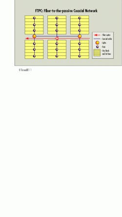
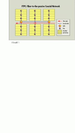
Though U.S. housing densities range from about 10 homes per mile in a country setting to well over 1000 in some dense urban areas, a reasonable lot size for the "average" U.S. neighborhood is approximately 100 ft wide. Including cross streets and back easements, a mile of coaxial network in this "average" service area will serve slightly less than 100 homes. An example is shown in Figure 1, which depicts a single fiber-optic node serving 72 homes passed.
There are several design parameters that determine the reach of a coaxial network, but all designs start with the minimum power and distortion specifications that will be allowed at the customer premises. These minimum allowable specifications are determined at the lowest level by the Federal Communications Commission. Most markets, however, will set higher standards in response to competitive threats and to allow for future applications such as 256 or 512 quadrature amplitude modulation (QAM). Once these parameters are set, they dictate the choices available in the rest of the network.
In Figure 1, the choice was made to design the system with an operational bandwidth of 750 MHz, 80 channels of analog NTSC video, and up to 33 QAM channels with speeds in excess of 42 Mbits/sec. Depending on the business plan, the network designer could stretch or shrink the actual coverage area significantly. For example, if the decision was made to supply 550-MHz worth of digital QAM channels and no analog channels, the reach of the fiber-optic electronics and the size of the single-node service area could be considerably larger.
The network in Figure 1 was designed to have a minimum 14 dBmV of signal output at 750 MHz, with a minimum carrier-to-noise figure of 48 dBc. A 0.625-diameter coaxial cable was used for distribution. The optical node had four equal outputs of 48 dBmV at the highest channel.
In today`s HFC equipment market, network frequency bandwidths are readily available at 550, 750, and 860 MHz. Because it contains no other active devices beyond the node, however, an FTPC network could be designed to almost any maximum bandwidth up to the frequency cutoff of the coaxial cable, which is well above 1 GHz. In reality, of course, this bandwidth expansion would face economic constraints related to serving-area size and electronics costs. In a network of this type, the delivered network capacity is as much dependent on the design and electronics in the optical plant as it is on the coaxial plant.
In what we refer to as a "traditional" HFC network, the ratio of fiber to coaxial-bearing plant is around 20% fiber to 80% coaxial cable. In an FTPC network, fiber expands to cover approximately 40% of total plant. At the same time, the average fiber count per foot is reduced, since there are more fiber-optic terminations with small fiber counts and more optical splitting in the field.
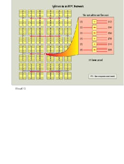
In Figure 2, the area covered has 511 homes passed. There are eight optical nodes serving the area. The fiber-optic plant is placed as efficiently as possible to feed the eight locations. If we placed two fibers from each optical node back to the headend or hub, the number of fibers would mushroom fairly quickly. For instance, if the nearest hub served 20,000 passings, it would have to accommodate 1906 fibers, not counting spares. Since there is no existing or proposed business application that might need that much capacity, some optical splitting lowers the overall cost without unduly limiting the future capacity. By splitting the fibers within a group of 500 passings to two groups of four in the forward direction and four groups of two in the reverse, the number of fibers needed to feed the area is reduced to six. The corresponding number of fibers at the hub is reduced to 240, a number in the same ballpark as traditional HFC.
The fiber splice and termination points must be managed in this architecture to keep labor costs within reason. One solution may be the use of pre-terminated pigtails that are lashed or buried in parallel to reduce the craft sensitivity and the number of splice housings. Such pigtails are readily available from several sources.
Last but certainly not least is the question of how to power the optical nodes. Since most of these nodes have power requirements of less than 1000W, they can be individually powered if the company`s business case allows it. If not, for a relatively small investment, several of these nodes could be tied together and powered by a larger power supply with coaxial cable. Since there are fewer devices than in standard HFC, there will be less power wasted from current and resistance.
An FTPC network is intuitively more reliable than a standard HFC network and consumes less power. And with only one type of active device in the plant, training and sparing issues can be greatly simplified. Assuming an operator continues to use the 5- to 40-MHz band for upstream traffic, managing it would also be easier, since the return groups would be smaller. At the same time, FTPC provides an operator with increased flexibility with regard to upstream spectrum; ways to take advantage of this flexibility are being explored by a number of equipment vendors. qFig. 2. The use of splitters in an FTPC architecture significantly reduces the number of fibers necessary to provide adequate coverage and reduces overall system cost.


