Modern colorless, directionless, contentionless, and flexible grid (CDC-F) ROADM networks have gained wide industry acceptance due to their flexibility, simplified operations, and improved efficiency. These new ROADM architectures automatically move, steer, and re-route wavelengths without the need for costly, time-consuming, manual changes required on previous generations of mux/demux-based ROADMs. Supporting flexible channel sizes, wavelength capacities, and baud rates, CDC-F ROADMs ensure carrier networks are compatible with current and future generations of coherent transponders. Since their introduction in 2016, the industry has a seen a dramatic shift to these newer, more modern, more flexible CDC-F ROADM architectures.
ROADM Add/Drop – Technology Engine
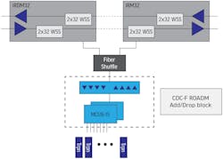
Modern CDC-F ROADM nodes are composed of ROADM line units, CDC-F add/drop blocks, transponders, and a fiber patch panel, also known as a “fiber shuffle” that provides interconnection between the functional blocks (Figure 1). Within the ROADM node, the add/drop block implements the CDC-F capability. The add/drop block enables any transponder to be connected to any incoming port (colorless), any port to be connected to any ROADM line degree (directionless), while avoiding wavelength interference (contentionless), all without requiring manual fiber changes or manual intervention. The add/drop block is the engine that powers a CDC-F ROADM node.
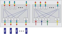
When first introduced, CDC-F ROADMs incorporated multi-cast switch (MCS) technology to implement the CDC-F add/drop architecture. As shown in Figure 2, an MCS module consists of an array of splitters, couplers, and optical switches. In the drop direction, wavelengths are split to each client-side port, where optical switches select the provisioned degree (i.e., direction). In the add direction, optical couplers simply combine all the wavelengths provisioned to the same WDM direction.
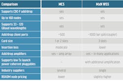
MCS modules are available in 8-degree configurations with 16 client ports (MCS8x16) and 16 degrees with 16 client ports (MCS16x16). Since MCS cards rely on simple power splitters and couplers, the insertion loss tends to be moderately high. Due to the high insertion loss, array amplifiers are needed in MCS add/drop blocks to provide acceptable optical power levels for the WDM line units, as shown in Figure 1.
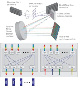
Recently, a contentionless MxN wavelength-selective switch (WSS) technology was introduced as another option to support CDC-F add/drop architectures. Within an MxN WSS unit, the optical splitters and couplers used in an MCS architecture are replaced by dual 8x24 or dual 16x24 WSS modules, as shown in Figure 3.
Replacing the optical splitters and couplers used in an MCS architecture with MxN WSS modules reduces the insertion loss. However, the larger, more complex MxN WSS components result in physically larger cards, typically requiring three-slot widths, along with slightly higher ROADM prices.
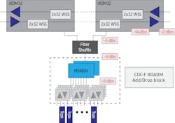
The MxN WSS can also be paired with amplified splitter/coupler cards to provide additional transponder port capacity, as shown in Figure 4. In this example, a single MxN WSS unit is paired with (1:4) amplified splitter/coupler cards to provide up to 96 client-side transponder ports per MxN WSS add/drop block.
MCS vs MxN WSS Comparison
The optical networking industry supports both MCS- and MxN WSS-based architectures, with both technologies providing the same colorless, directionless, contentionless, flexible-grid interconnections between transponders (or alien wavelengths) and WDM line degrees. While MCS- and MxN WSS-based architectures offer similar operation and performance, there are important differences with each technology (Table 1).
MxN WSS-based architectures are ideal for nodes with very large add/drop port requirements. When combined with amplified splitter/coupler cards, MxN WSS architectures can support up to 1000 transponder ports. As with MCS-based systems, MxN WSS modules are also available in both 8D and 16D configurations.
As a result of their more complex underlying technology, MxN WSS cards tend to be higher priced and a slightly larger than MCS options. In addition, the MxN WSS components are currently single-sourced in the industry.
Optical Performance Comparison
Ensuring proper optical power levels within each ROADM stage is critical to both ROADM and network performance. System vendors pay particular attention to two key optical power parameters:
- Per-channel power levels at the input to the WDM line units (add direction)
- Per-channel power levels into transponder Rcv port (drop direction)
Both power levels must be controlled within acceptable ranges for proper ROADM operation. When the losses through the add/drop stage become too large, or the incoming transponder Tx power levels are too low, additional amplification (gain) is required in the add/drop stage to maintain acceptable per channel power levels.
MCS units have moderately high insertion losses, requiring amplifier arrays in MCS add/drop blocks to boost the optical power levels, as shown in Figure 1. One of the rationales for MxN WSS-based architectures was the hope that the lower MxN WSS insertion loss might preclude the need for amplification in the MxN WSS add/drop block. Unfortunately, many MxN WSS-based applications will require similar add/drop amplification to ensure proper internal power levels and achieve comparable OSNR performance.
A short example highlights how optical power levels affect ROADM add/drop architectures and internal amplification requirements. The red boxes in Figure 4 indicate the per-channel power levels needed in the add direction to meet the -14-dBm egress amplifier power target. Based on the worst-case insertion losses of the WDM line card, the fiber patch panel, and the 8x24 MxN WSS add/drop stage, transponders with approximately +5-dBm Tx power are required for direct connection into the MxN WSS add/drop block. While there are transponders incorporating transmit amplifiers (EDFAs) and supporting up to +5-dBm output power, many transponders fall within a more typical range of -2 to +2 dBm output power. These nominal industry transponders, as well as the newer coherent pluggable modules (400ZR/ZR+), require some type of additional amplification in the MxN WSS add/drop block to meet the power requirement of the ROADM line units and to avoid optical signal-to-noise ratio (OSNR) penalties that result from operating at power levels that are too low.
In addition to maintaining proper optical power levels within a ROADM, there are a number of additional parameters that affect wavelength OSNR and overall network performance, including:
- Power-level balance across wavelengths within the same add/drop block
- Transponder OSNR specifications
- Transponder out of band (OOB) noise specifications (MCS)
- WSS port/channel isolation (MxN WSS)
- Polarization-dependent loss (MxN WSS)
Each of these parameters affects the OSNR penalty applicable to WDM network designs. Some of these issues affect MxN WSS-based architectures more (WSS port isolation, polarization-dependent loss) and others have more impact on MCS-based systems (OOB noise). In general, with proper optical power level management within the ROADM node, OSNR penalties due to these other factors can be limited to manageable levels with either MCS or MxN WSS architectures.
Pricing Differences
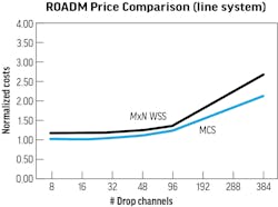
While both MCS and MxN WSS methods provide similar CDC-F interconnections between transponders and WDM line units, there are pricing differences between the two architectures. The pricing comparison shown in Figure 5 is for comparable 8D CDC-F ROADM nodes: 1) an MCS-based ROADM with MCS add/drop blocks and amp arrays, and 2) an MxN WSS-based ROADM using MxN WSS (8x24) add/drop blocks with amplified splitter/coupler cards. Transponders were not included in the models, since they would be common to both systems.
The MCS architecture results in an approximately 15% lower priced ROADM node than MxN WSS alternatives. The pricing difference is likely due to that fact that MxN WSS modules are a relatively new technology and incorporate more complex, dual 8x24 WSS technology.
Coherent Pluggable Impacts
While there has been significant industry interest in 400ZR/400ZR+ coherent pluggable modules, especially for use in metro point-to-point data center interconnect (DCI) applications, these small-sized coherent pluggables impose issues when used over general-purpose metro and regional CDC-F ROADM networks (see Lightwave, Understanding 400ZR/OpenZR+/400ZR+ Optics).
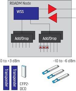
Due to their small size and limited power dissipation, coherent pluggables have much lower Tx launch powers (-10 dBm) and lower Tx OSNR (~34 dB) than comparable card-based transponders, which typically support 0 dBm Tx power and 45 dB OSNR.
In addition to managing per-channel power levels at each stage within a ROADM node, the power levels across channels must be balanced to within a few decibels to ensure optimal node and network performance. The wide range of incoming power levels from new 400ZR/400ZR+ modules (-10 dBm) and traditional card-based transponders (0 to +5 dBm) will likely require segmenting channels into separate ROADM add/drop blocks based on incoming power levels as shown in Figure 6.
Future-Proofing Optical Networks
The additional optical layer flexibility provided by CDC-F ROADMs enables powerful new optical layer protection and restoration techniques, improves network capacity and utilization, and reduces overall networking costs. Network operations that once required costly, time-consuming, manual changes can now be fully automated.
Both MCS and MxN WSS technologies functionally perform the same CDC-F function for ROADM add/drop architectures and both can be configured to provide similar network performance. MCS- based architectures are offer slightly lower ROADM node costs than MxN WSS versions and result in slightly smaller physical node sizes. MxN WSS-based systems can support very large add/drop port counts (> 600 ports) and are better suited for use with new, low Tx power coherent pluggables, when coupled with amplified splitter/coupler cards. Many MxN WSS-based applications require some type of add/drop amplification, similar to existing MCS-based systems, to ensure acceptable optical power levels within the ROADM. Fortunately, the optical networking industry supports a wide choice of both MCS and MxN WSS ROADMs, including vendors who provide both options as part of their WDM product portfolios.
Randy Eisenach is part of the WDM and High Speed Optics Product Management team at Nokia. He specializes in optical transport technologies, next generation ROADM architectures, and high-speed photonics. Randy has over 30 years of optical transport and networking experience and has held a wide range of senior level positions in systems engineering, product management, and product marketing. He has authored several papers and spoken at many industry conferences.
