Will your 25-GHz filters stand the heat?
Environmental challenges face high-spectral-density networks; properly athermalized fiber Bragg gratings could be the solution.
ERICK PELLETIER, RICHARD L. LACHANCE, and MICHEL MORIN, TeraXion Inc.
In response to the ever-increasing demand driven by the Internet, optical communication networks evolve continuously toward higher transmission bandwidths. From a few channels at 2.5 Gbits/sec, systems are now deployed with tens of channels at 10 Gbits/sec. The maximization of the DWDM and TDM technology mix is evolving in three major trends: an increase in bit rates (systems with transmission rates of 40 Gbits/sec per channel are being introduced), a widening of the transmission band (S- and L-bands are now available for transmission), and a narrowing of the channel spacing (from 200 GHz to 25 GHz).
As system manufacturers continue to increase the transmission bandwidth, component and subsystem manufacturers must push current technologies to their limit. The increase in bit rate translates into a commensurate increase in the signal bandwidth. This trend clashes with the narrowing of the channel spacing, which leaves less and less room to accommodate the signal bandwidth. A signal modulated at 10 Gbits/sec (non-return to zero) has a spectral width of about 20 GHz (160 pm @ 1,550 nm).
As we evolve toward DWDM systems with 25 GHz (200 pm) and lower channel spacing, the requirements for optical performance become very tight. The individual channel filters must maintain the passband accuracy while preventing crosstalk from the adjacent channels over the operating temperature range. That can only be achieved with high-performance spectral filters that operate stably under changing environmental conditions. When properly athermalized, fiber Bragg gratings (FBGs) can deliver the spectral performance required by high-bandwidth transmission networks.
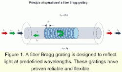
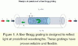
An FBG consists of a periodic modulation of the index of refraction along the core of an optical fiber. It is created by exposing a photosensitive fiber to a properly shaped intensity pattern of ultraviolet light. The resulting grating reflects selectively the light guided by the optical fiber at the Bragg wavelength lB=2nl , where n and l are the effective index of refraction of the fiber and the period of the grating in the fiber (see Figure 1).Its reliability and all-fiber nature, as well as the afforded flexibility in tailoring the reflectivity spectrum, make the FBG an ideal spectral filter for fiber-optic system applications. It is used extensively in optical communication systems for DWDM, chromatic-dispersion compensation, gain flattening in optical amplifiers, and for stabilizing the frequency of semiconductor lasers. This technology allows the fabrication of highly selective filters and will play a key role in future DWDM systems.
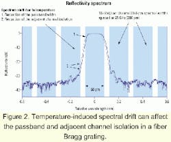
In fact, FBG filters allow better bandwidth efficiency than any other technologies used in DWDM systems. Figure 2 shows the reflectivity spectrum of a 25-GHz FBG characterized by a flat-top response and a steep rolloff (10-Gbit/sec transmission channels with 25-GHz spacing are also represented). This Figure also shows the effect of a spectral drift due to temperature on both the passband and adjacent channel isolation.Unpackaged FBGs are sensitive to temperature variations. Both the refractive index and the grating period vary nearly linearly with the ambient temperature. As a result, the Bragg wavelength of an uncompensated FBG produced in a standard fiber increases with temperature at a typical rate of 10 pm/°C in the 1,550-nm region.
In DWDM systems, optical filters for adding/dropping optical channels must retain their high wavelength accuracy notwithstanding changing environmental conditions. In systems operating at a channel spacing of 25 GHz, the thermal sensitivity of uncompensated FBGs would restrain the operational range to 1 or 2°C, which is clearly too restrictive. (The operating temperature requested by system manufacturers typically ranges from -5°C to +70°C.) For the accurate and reliable long-term operation of these devices, suitable temperature-compensation techniques are a necessity.
Different stabilization techniques have been proposed in the past to overcome the intrinsic thermal sensitivity of FBGs.1 Methods applicable to the telecommunications field can be either active or passive. Active stabilization involves the continuous monitoring and the dynamical control of a given parameter. For example, the grating temperature can be maintained actively above the expected maximum ambient temperature with devices such as Peltier elements. In other systems, the Bragg wavelength is monitored continuously and corrected by straining the fiber with piezoelectric elements.
While effective, active thermal stabilization is costly to implement, its complexity leads to reliability concerns, and the power consumption of control circuits represents a major handicap. In general, preference is given to passive compensation, which is much simpler and requires no power source.
Passive compensation devices control the elongation with temperature of the optical fiber containing the FBG. The fiber is clamped to a mechanical structure that imposes upon it a negative elongation as the temperature increases. This contraction of the fiber compensates for the increase in its index of refraction with temperature, thus allowing a stabilization of its Bragg wavelength against temperature fluctuations.
Conceptually, this is most simply achieved by attaching the fiber containing the FBG to a material with a suitable negative coefficient of thermal expansion (CTE). In practice, this approach suffers from major drawbacks. The CTE must be accurately matched to the optical-fiber properties, a requirement that can be met only through careful control of material formulation. It must also be constant from one sample of material to another, which is difficult to achieve in practice. Such materials are difficult to machine without spoiling their properties, and in particular without altering their CTE. Also, problems may occur with the supply of those exotic materials.Passive temperature compensation can also be achieved through the principle of differential expansion. Here, the fiber is clamped to a structure made of materials with different, but usually positive, CTEs. The elements with different CTEs are mounted in such a way as to impart a contraction to the fiber when the temperature increases. The fiber must remain under tension between the points of attachment to the structure to ensure that its length is indeed controlled by the structure.
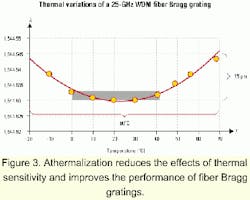
The accurate design of such a system requires knowledge of the thermal properties of the fiber and the materials involved, and must take into account the effect of stress on the refractive index of the fiber. A properly designed system can reduce the thermal sensitivity of an FBG by an order of magnitude. Figure 3 presents the variation of the center wavelength of a 25-GHz WDM filter athermalized with such a system. This filter shows a maximum variation of 15 pm over 90°C.
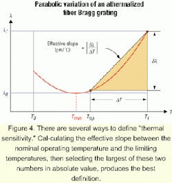
As observed in Figure 4, the thermal sensitivity of an athermalized FBG will in general vary with temperature. In particular, the Bragg wavelength of an FBG athermalized by a differential expansion structure displays a parabolic dependence with temperature. This behavior stems from the temperature dependence of the thermal properties of the optical fiber and of the materials used for the athermalization. At the bottom of the parabola, the rates of variation of the length and index of refraction of the optical fiber perfectly compensate each other. Unfortunately, these rates vary with temperature and the compensation is thus partially lost at other temperatures. Users should be aware of this behavior when interpreting thermal sensitivity specifications.Figure 4 presents the generic dependence of the Bragg wavelength of an athermalized FBG. Temperatures T0 and T1 define the temperature range of the operation of the device (e.g., -20°C, +70°C), whereas Top represents the expected usual temperature of operation (e.g., 22°C).
The thermal sensitivity is sometimes defined as the slope between the minimum and maximum temperatures. That can lead to a misleadingly small number, especially if T0 and T1 are symmetrically located with respect to the minimum of the parabola. This number amounts to averaging the slope over the whole range of temperature, a procedure with little relevance given the change in sign of the slope taking place between T0 and T1.
The thermal sensitivity also is sometimes specified as the total wavelength range divided by the total temperature range. This number again has little predictive value and can lead to under-evaluations of the thermally induced variations in the Bragg wavelength. As the thermal sensitivity is closely related to the compensation technique, this specification should be carefully interpreted.
A better thermal sensitivity definition allows users to extrapolate the performances of FBGs at the extremes of the application range and answers the following question: Will the Bragg wavelength move outside of allowed limits at any point within the temperature range of operation? The effective slope is calculated as shown in Figure 4 between the nominal operating temperature Top and the limiting temperatures T0 and T1. The thermal sensitivity of the FBG is taken from the largest of these two numbers taken in absolute value. Standard temperatures used are as given above, but they can also be specified by the customer. The thermal sensitivity thus defined will allow users to properly assess the suitability of athermalized FBGs for their applications.
The combination of narrow channel spacing and high transmission rates leads to stringent system requirements for filter performance. Fiber Bragg gratings represent a key technology for future DWDM systems. As FBG devices are intrinsically temperature sensitive, they must be properly packaged to reduce thermally induced wavelength drifts. Efficient passive thermal stabilization of FBGs is achievable using a differential expansion structure. The resulting athermal filter shows a parabolic wavelength drift with temperature. System designers should be aware of this behavior.
Superior athermal package design is mandatory for FBG DWDM filters, as well as for other components such as gain-flattening filters. The challenge for filter manufacturers will be to provide highly reliable and well-athermalized packages, while keeping dimensions small enough to meet systems manufacturers requirements.
Dr. Erick Pelletier is product management director, Dr. Richard L. Lachance is research and development program manager, and Dr. Michel Morin is senior scientist at TeraXion Inc. (Sainte-Foy, Quebec). They can be reached by phone at 418-658-9500, by fax at 418-658-9595, or by e-mail at [email protected].
D. Weidman, "Fiber Bragg gratings enhance real-world applications," Laser Focus World, pp. 99-103, March 1999.
