New laser design for swept wavelength measurement systems
Testing multichannel devices by fast and easy means.
ULRICH WAGEMANN, Agilent Technologies
Telecommunications is a dynamic, high-growth business that relies on continuing technological innovation, particularly to satisfy increasing bandwidth requirements. Today, DWDM technology offers the preferred solution to meet these capacity needs. DWDM technology works by sending multiple modulated wavelengths (channels) down a single fiber-optic cable.
As DWDM technology evolves to squeeze more channels into a single fiber, so do the challenges for the component manufacturers charged with designing, manufacturing, and testing optical components. Passive components with channel spacing of 20 pm have been reported. This development goes hand-in-hand with steeper filter functions, which means test procedures that have limited wavelength resolution, or accuracy, don't yield sufficient results.
The choice for testing these components for loss over wavelength, especially for multichannel devices, is using a tunable-laser source operated in swept mode and a broadband receiver such as an optical power meter. This method is an attractive option for the manufacturing industry, because it offers the shortest measurement time by measuring all channels in parallel. A new laser design with a low-noise cavity and a built-in real-time wavelength meter has demonstrated ease of use for designing test solutions for passive optical components.
The huge demand for fiber-optic components, driven by the steady growth of bandwidth requirements, is forcing manufacturers to increase their production throughput dramatically. In research and development, time-to-market is most important, whereas in manufacturing, throughput and test time are the key drivers, calling for a scalable test setup.
For passive optical components, many parameters can be tested using a small set of basic measurements. Typically, a loss over wavelength trace is recorded and analyzed to characterize a passive component like a filter. However, the specified performance of a given parameter can't be better then the inherent uncertainty of the test system. It is therefore usually preferable to achieve the highest possible accuracy for a test procedure that can be afforded in terms of test time or investment. The result is better specifications for the parameter in question, reduced test uncertainties, or higher component yield.With DWDM, the ever-increasing number of channels1 intensifies the challenges of designing, manufacturing, and testing the optical components that perform the multiplexing, demultiplexing, and routing of individual channels. A demultiplexer capable of separating dozens of narrowly spaced wavelengths presents a formidable challenge for traditional test and measurement methods. The testing of a demultiplexer is a typical example of a whole family of today's passive optical components with a common input and a couple of outputs.
In most loss tests, two measurement cycles are required: a reference measurement without the device under test (DUT) and another with the DUT. Usually, this test has to be carried out for a whole wavelength range to prove that a device is not wavelength-dependent (broadband device) or to determine wavelength dependency (narrowband device).
From a loss trace, the most relevant parameters can be extracted, including insertion loss, passband ripple, center wavelength, and crosstalk. The test for polarization-dependent loss is also based on loss-over-wavelength measurements. This test can be carried out by adding a state-of-polarization controlling device into the setup and evaluating the resulting measurement data.2
WDM has not yet reached its limits. Essentially, there are three ways to increase data transfer through a fiber: increase the transmission bit rate of each channel, use wider transmission windows, or simply use more transmission channels.
Demultiplexers consisting of cascaded Mach-Zehnder interferometers with channels separated by no more than 20 pm, or 2.5 GHz, have been developed.3 This passive-optical-component test example will illustrate how measurement methods with a limited wavelength resolution, linearity, or accuracy do not lead to sufficiently accurate test results.
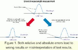
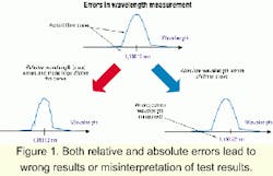
With the advent of WDM, the question is no longer whether wavelength-dependent testing is necessary, but which wavelength accuracy is needed and which method is best suited to perform the wavelength testing. It is no surprise that the most important parameter to be controlled in wavelength multiplexing is the wavelength. Both relative and absolute errors in measuring the wavelength's filter curve lead to wrong results and can cause misinterpretation of test results (see Figure 1).
Modern components can have a dynamic range of 60 dB or more, so measurement methods must provide a high dynamic range, as well. The methods presented here address both problems: dynamic range and wavelength accuracy.
A simple, generic test setup consists of a source, DUT, and receiver. The use of a broadband source and an optical spectrum analyzer as a receiver is a common method of testing. This arrangement is well known and shows a high dynamic measurement range. But when multiple channels need to be tested, this approach requires that the channels be switched, slowing the measurement speed of the test procedure. Even more important, the resolution of this method is limited to a few picometers.
Using a tunable source and broadband receiver (photodiode) overcomes the problem of limited resolution but has the drawback of source noise reducing the dynamic range for a loss measurement. Before delving into technical details and problem solutions, it is worth taking a closer look at the instrument's data sheets. The most important parameters for tunable lasers are wavelength performance-absolute and relative accuracy-and output power.
The definition of "absolute wavelength accuracy" is simple: It's the difference between what is displayed and what the laser really emits. The difference is typically between a few and about 100 pm. A good "relative accuracy" means that if the laser is tuned by 50 nm, it really tunes by 50 nm. But if the starting point, which is absolute accuracy, is not known, relative accuracy does not always help (see Figure 1).
Due to today's high receiver sensitivity, maximum output power is of limited importance, and a test method offering highest dynamic range is much more significant. In addition, good power and wavelength stability and repeatability are necessary. Remember that for an insertion-loss measurement, two traces are needed-one for reference, one for measurement-and if the power level or wavelength of the sources varies between the two measurements, errors might occur.
Although there are many tunable lasers on the market today, external-cavity lasers (ECL) with a semiconductor diode as gain medium provide the best compromise of tuning range and performance.4 ECLs are widely used in optical-component testing.All laser diodes show the effect of source spontaneous emission (SSE), which is the sum of all spontaneous transitions and therefore shows a broad wavelength characteristic comparable to an LED. SSE is small compared to the laser line-a typical level between signal and the total noise is 1,000: 1, or 30 dB. Unfortunately, SSE affects the measurement of optical components.
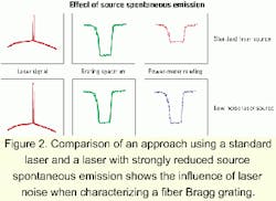
Figure 2 illustrates the effect of SSE. A fiber Bragg grating is tested using a tunable laser and power meter. While the laser is sweeping over the filter's rejection band, the laser line is strongly attenuated, but the photodiode receives all spontaneous emission, which is able to pass through the passbands of the filter. Because a photodiode integrates over all wavelengths, a convolution of the spectral source characteristic and filter response results, and the power meter does not detect the true filter shape. From this analysis, it can be easily seen that the power meter would be able to detect the true filter shape, if only minimum SSE was emitted by the source.The solution is to have a special laser-cavity design that can separate the SSE noise from the desired signal. Using the well-known principles of Metcalf-Littman in the design, the cavity is placed between the mirror and partially reflecting backside of the laser chip, and a grating acts as a wavelength discriminator. Simultaneously moving the grating and mirror generates mode-hop-free tuning of 100 nm or more.4
While SSE is a characteristic of all laser chips, it is possible to couple an almost noise-free signal out of a tunable laser based on external-cavity design. That's because the grating acts to disperse the broad noise floor, making sure it doesn't travel in the direction of the amplified signal wavelength.5
An important feature of the laser-cavity design is that it's possible to measure all channels of a component with the highest channel count by the simplest means-through the use of photodiodes.
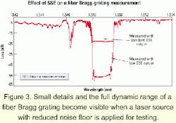
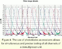
Figure 3 depicts the effect of low SSE on a real-life measurement of a fiber Bragg grating. A low SSE source ensures that the true filter shape is detected. This example shows clearly how the measurement dynamic is enlarged by almost 30 dB. In addition, small details in the notch are detectable, which remained hidden when a standard laser was used to take the measurement.Figure 4 shows the extension of the measurement to a 16-channel demultiplexer. Demultiplexers have to be characterized by a range of critical parameters such as bandwidth, channel spacing, insertion loss, and crosstalk. In this example, the device exhibits a dynamic range of 70 dB. Undesired crosstalk especially is a critical inhibitor of reliable data transmission. Crosstalk results in the overlap of a wavelength to multiple channels, reducing signal quality. A low SSE ensures that all the essential parameters, including crosstalk, are determined correctly.
Note that all channels are measured in parallel. A trigger from the laser reads out power-meter values during the laser sweep, while the wavelength information is provided through a real-time wavelength meter.
Any measurement procedure for today's passive components must include the ability to perform at the highest wavelength accuracy. This requirement is driven by rapidly decreasing channel spacing and corresponding filter traces.
A low-SSE source enables analysis of all the filter shape details (see Figure 4). For the filter designer, these details are important hints for understanding and improving the manufacturing process. But this information is of limited use, if the details show up at the wrong wavelength or their position is not reproducible. The problem at hand is measuring the wavelength precisely at a sufficient speed. Usually, wavelength meters are applied, since these devices provide excellent results in the picometer range or below. Unfortunately, these devices are too slow for these particular wavelength measurement tasks.To overcome this problem, many procedures have been proposed to measure wavelength: one is to use the well-defined absorption peaks of an acetylene gas cell, another is to use fringe counting of an etalon-or a combination of both procedures.
A new approach6 is to use a combination of a retarder plate and polarizing beamsplitter as the wavelength-selective element. What happens if the wavelength is tuned? To understand, it's best to think of the retarder plate as an etalon with a small finesse-the transmission parameter resulting from the reflectivity at etalon boundaries. The net effect is for a wavelength change to show up in a sinusoidal intensity function, and not in integer fringes. Adjusted properly, a retarder plate can act as two slightly de-tuned etalons simultaneously for two orthogonal polarization states due to the different refractive indices of the small and fast axis. From this characteristic, it is possible to extract a very sharp criterion for wavelength change with the help of two simple photodiodes. The setup is calibrated and can provide wavelength information at the highest speed, which is only limited by the applied electronics.
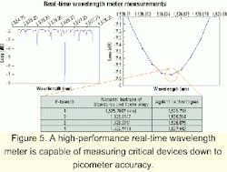
In Figure 5, an acetylene gas cell was chosen as the test object. The absorption peaks of acetylene are very sharp; their positions are well known and National Institute of Standards and Technology-traceable.7 A tunable laser and power meter were used to record the spectral absorption of this cell. Figure 5 compares typical measured data to published calibrated data and shows an excellent agreement.
In another experiment, analysis of repeatability was tested using the gas cell. A flank of an absorption peak was used as criterion. From the measurement traces, a repeatability of approximately ±0.15 pm was deduced.
It is important that powerful measurement solutions are available, not just good instruments, especially for the manufacturing environment. Users do not have much time to study a manual and program their own test solutions. Since virtually all these systems have to be automated, a considerable amount of optical as well as software engineering knowledge is necessary to accomplish such a task. Test systems used in research and development might have different requirements than those designed for use in volume manufacturing; time is more critical in production, whereas maximum instrument performance might be preferred in research and development.
Instrument drivers can help speed up the process of programming new tasks. These drivers come with a set of predefined, easy-to-use functions and can help reduce the engineering effort. Some product lines can be controlled by any computer platform (PC, Macintosh, Unix, etc.) equipped with a general-purpose interface bus card. With these test instruments, a predefined VXI plug-and-play (PnP) instrument driver with built-in functions replaces hundreds of individual standard commands for programmable instruments and makes the job of writing instrument control programs easier.
The PnP driver is a dynamic library that can be linked into many programming languages and consists of many basic functions and applications. PnP drivers can be linked into software languages such as HP VEE (Agilent VEE), Lab View, LabWindows, VisualBasic or VisualC++. These drivers best support powerful hardware functions such as high-speed, high-accuracy wavelength logging.
The most important measurement function is the use of a wavelength sweep and the simultaneous recording of power-meter values, called a "wavelength scan." A "multiframe wavelength scan" allows more than one mainframe to be connected and to synchronize, for example, power readings from different mainframes. That is key to enabling high-channel-count test solutions. Up to 1,000 power meters can be addressed.
Instrument drivers not only make life easier during the development phase and increase throughput, but they also deliver a value-add in terms of measurement performance.
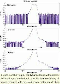
Because of the high dynamic needed to measure filter devices (see Figure 3), a power meter cannot be kept in the same power range for all data points. An auto-ranging feature can't be used in this case because the ranging process takes too much time. Sometimes this problem is addressed by "logarithmic" power meters. These devices use a logarithmic amplifier in the analog path to extend the dynamic range. However, this solution sacrifices power resolution and power linearity.The solution proposed here is called "stitching." Depending on the dynamic needed, the tunable laser performs more than one sweep. For each sweep, the power meters are kept in a fixed range to avoid the time-consuming range process. This fixed range is changed to a more sensitive level for every sweep, and the results are stitched together after the last sweep (see Figure 6).
This multiscan and stitching process is completely transparent to the user or programmer. The only user-specified parameter is the number of scans to be performed and the mainframes hosting the power meters.
A laser-based test system, which meets today's measurement requirements, entails a laser with a built-in real-time wavelength meter, a low-noise cavity, and powerful instrument drivers. This laser design offers ease of use for building test solutions for passive optical components. The test results here demonstrate that sophisticated but simple approaches can be used to characterize passive components quickly and precisely.
Ulrich Wagemann is product manager for tunable-laser sources at Agilent Technologies (Böblingen, Germany). The author wishes to thank all members of the Agilent tunable-laser team, especially Edgar Leckel and Emmerich Müller.
- K. Takada et al., "10-GHz spaced 1010 channel AWG filter achieved by tandem connection of primary and secondary AWGs," PD3-8, ECOC 2000.
- D. Derickson (ed), Fiber Optic Test and Measurement, Prentice Hall 1998.
- Joseph Chon et al., "Expandable 50-GHz and 100-GHz dense wavelength division multiplexers based on unbalanced and cascaded-fiber Mach-Zehnder architectures," NFOEC 1999.
- F.J. Duarte, Tunable Lasers Handbook (Optics and Photonics), Academic Press.
- E. Leckel et al., "Impact of source spontaneous emission (SSE) on the measurement of DWDM components," OFC 2000, Baltimore, WB4.
- Emmerich Müller et al., "Fast and accurate determination of a tunable laser wavelength and its application to DWDM components," OFC 2000, WB2.
- S.L. Gilbert and W.C. Swann, "Accurate wavelength calibration references for wavelength division multiplexing," OFC 99, ThS2.
