New approaches to interleaver, dispersion management, and DWDM technology
Components and subsystems based on innovative technologies will enable participation in the optical-network build-out.
BY CHRISTOPHER LIN and DR. SIMON CAO, Avanex Corp.
Optical communications systems offer unprecedented bandwidth capacity for exploding data traffic demands. Carriers are upgrading to DWDM networks to avoid the costs of laying new fiber and taking advantage of optical amplifiers to bypass unwieldy optical-electrical-optical (OEO) conversion for signal regeneration. Optical amplifiers enable economical use of high-channel-count DWDM networks because each channel does not need to be regenerated through OEO conversion.
As DWDM channel counts continue to increase, however, wavelength addressing becomes a more promising signal routing tool. In this type of network, signal destination is denoted by wavelength; therefore conversion of the signal from optical to electrical to determine the intended destination is not required. By incorporating this routing function, carriers can reduce construction and operational costs by removing some of the routing burden from electronic routers. Use of this routing function also permits multiple protocols on the same network without the interface overhead.
Between the transmitter and receiver, the all-optical network must perform four functions: wavelength routing, dispersion management, amplification, and diagnostics. Wavelength routing consists of DWDM, optical add/drop multiplexing (OADM), and switching by optical crossconnects. Dispersion management includes chromatic-dispersion compensation and dispersion-slope and polarization-mode dispersion compensation. Amplifiers need to maintain good optical signal-to-noise ratios (OSNR), avoid nonlinear effects, and ensure equal gain over all channels. Diagnostics include monitoring to detect channel presence as well as power and quality levels and protection switching to ensure continuation of network operation in the event of a failure.Many of these network functions can be supported using adaptations of existing technological platforms to new problems or using entirely new approaches. We'll look at a suite of distinctive technologies-birefringent Gires-Tournois (BGT) interferometer, virtually imaged phased array (VIPA), and concave holographic grating-and their applications in all-optical networks.
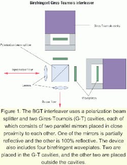
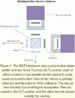
DWDM can be performed using a number of devices, including thin-film filters, fiber Bragg gratings, array waveguides, Echelle gratings, and bulk gratings. Furthermore, any of these devices can be combined with an interleaver. An interleaver segregates a group of channels into odd and even sets. A group of n channels spaced 50 GHz apart can be separated into two sets of n/2 channels spaced 100 GHz apart. Of course, interleavers can be cascaded to produce even coarser separation. By increasing the spacing between channels, the design difficulties of any of the previously mentioned devices are decreased. Once a group of channels has been demultiplexed, fixed OADM is straightforward, and reconfigurable OADM only requires some simple switches. Optical crossconnects provide nxn switching from one fiber array to another.The BGT interferometer is a new type of interleaver. It is similar in layout to a Michelson interferometer. Instead of a beam splitter and two mirrors, the BGT interferometer uses a polarization beam splitter (PBS) and two Gires-Tournois (G-T) cavities. A G-T cavity consists of two parallel mirrors placed in close proximity to one another. One of the mirrors is partially reflective and the other is 100% reflective. The BGT interferometer also includes four birefringent plates. Two of these waveplates are placed in the G-T cavities, and the other two are placed outside the cavities (see Figure 1). The orthogonal optical axes of the waveplates are set at 45 degrees with respect to the s and p polarizations defined by the PBS. In effect, the waveplates function as a 50-50 beam splitter so that the s and p polarizations are each split into two equal beams traveling through the same physical space but on different optical paths because of the birefringence of the waveplates. Upon return to the PBS, the two component beams of the s and p polarizations are recombined as sum and difference beams. One beam is reflected by the PBS, while the other is transmitted-and vice versa for the other cavity-so that all odd channels exit left and all even channels exit down. In fact, if the input polarization is controlled, using well-known methods, only one G-T cavity and one pair of waveplates are needed.
The BGT interferometer possesses three desirable features: The bulk of propagation through the interferometer is through free space. It uses self-beam interference. And it offers better performance than commercially available alternatives.
The advantage of propagating through free space is that there is no index change with respect to wavelength and very little index change with respect to temperature. The G-T cavities are air cavities so that dimensional change with respect to temperature is minimized. The waveplates are thin enough so their deviations over temperature and wavelength are mitigated.The two beams that ultimately interfere with each other travel through the same physical space. The path-length difference is created by the use of birefringent plates. Since the two beams travel through the same physical space, the only important dimensions in the interferometer are the widths of the waveplates and size of the cavities. The placement of the PBS, waveplates, and G-T cavities with respect to each other is inconsequential. When the temperature changes, the induced change in position of the various parts of the interferometer with respect to one another has no implication on performance. Moreover, this self-beam interference simplifies manufacturing since these positional relationships are not critical.
Finally, material, thermal, and manufacturing issues aside, the BGT interferometer simply produces a better interleaver than other techniques, including bulk birefringent crystals, cascaded Mach-Zehnder interferometers, compound Fabry-Perot interferometers, and Michelson interferometer derivatives. The two fundamental specifications of interleavers are passband width and stopband width. Given a passband and stopband definition, for example, -0.5 dB for passband and -20 dB for stopband, the BGT interferometer can simultaneously produce a wider passband and stopband than any of the other techniques.
Dispersion management devices are currently restricted to chromatic-dispersion compensators and dispersion-slope compensators. Polarization-mode dispersion (PMD) is typically a problem for long-distance and high-bit-rate systems operating on the installed base of conventional singlemode fiber. PMD problems can be avoided by deploying new fibers specially designed to limit PMD. Chromatic dispersion is usually corrected using dispersion-compensating fiber (DCF). Other approaches include the virtually imaged phased array (VIPA), fiber Bragg gratings, and higher-order-mode fibers.
The VIPA can be used for dispersion slope as well as PMD compensation. Dispersion slope has started to become a problem because of increasing spectral usage. As DWDM becomes increasingly prevalent, the spectral distance between the extreme channels and center channel increases until the deviation between the residual dispersion-because of slope mismatch between the compensator and singlemode fiber-and the ideal dispersion compensation at the center channel becomes large enough to restrict bit-rate or transmission distance. The only technology other than the VIPA that can handle dispersion-slope compensation is specially engineered higher-order-mode fiber.
After traveling 80 km or so, an optical signal needs to be amplified and compensated. The insertion loss added by enough DCF to compensate an 80-km length of singlemode fiber is roughly 10 dB. If the signal is not amplified before it is sent through the DCF, the signal will fall dangerously close to the noise floor.
The only readily available optical-amplifier technology is the erbium-doped fiber amplifier. Raman amplifiers are maturing and should be available in the near future. The advantages of the Raman amplifier are a wider spectrum of operation and less amplified spontaneous emission, or noise. The primary problem with Raman amplifiers is the safety of the necessary high-power pump lasers. Aside from raw gain and low noise, amplifiers need to amplify all channels evenly, which typically involves a gain-flattening filter. In static networks, this filter is easy to design and manufacture. In dynamically reconfigurable, long-haul, DWDM networks, dynamic gain equalization is required.Unequalized gain will cause excessive channel-power imbalance. In a long-haul link, including dozens of gain blocks, excessive power imbalance will cause unacceptable deterioration of the under-amplified channels. Experimental methods to provide this function include demultiplexing the DWDM channels using an arrayed waveguide grating (AWG) and attenuating them individually or cascading acoustically tunable fiber-based notch filters.
A simpler but related problem to gain equalization is the "smart" OADM function. OADM modules must be able to set the power level of the added channel using a variable optical attenuator equal to that of the dropped channel to prevent the same excessive power imbalance caused by unequalized gain.
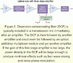
DCF is typically included in a transmission link immediately after an amplifier. The DCF is then followed by another amplifier and could even be followed by an OADM module and yet another amplifier (see Figure 2).
Unfortunately, DCF has a very narrow core diameter. If the gain of this first-stage amplifier is too large, the power density in the DCF will be large enough to produce nonlinear effects such as four-wave mixing and cross-phase modulation. These phenomena contribute to degrade signal quality.
In practice, the gain of the pre-DCF amplifier in a network node must be reduced below the maximum gain available in that amplifier. That is particularly unfortunate because the OSNR of a group of cascaded amplifiers (potentially as many as three) is dominated by the OSNR of the first amplifier. Since the VIPA compensator is a micro-optic device with a spot size that is multiple orders of magnitude larger than that of DCF, there is no danger of sufficiently high power density to cause nonlinear effects. In fact, swapping a VIPA dispersion compensator for DCF can boost the transmission distance of a metro amplifier from 80 to 100 km.
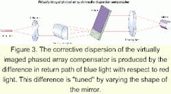
A VIPA chromatic-dispersion compensator typically consists of a collimator, a line-focusing lens, a tilted etalon with 100% coating on one side except for an antireflection (AR) coated window and a high-reflectivity (HR) coating on the other side, a focusing lens, and a mirror (see Figure 3). Line-focused light incident on the AR-coated window of the tilted etalon bounces back and forth between the 100% and HR coatings of the etalon. The multiple reflections can be interpreted as an array of virtual images positioned at intervals of twice the thickness of the etalon. The interference of these virtual images produces large angular dispersion. Blue light travels upward upon exiting the etalon and red light travels downward. The light is focused onto the mirror by the focusing lens. The mirror reflects the light back into the etalon. Blue light is reflected high up the etalon and must bounce back and forth many times along the etalon until it can exit through the AR-coated window and return to the fiber. Red light is reflected low on the etalon and does not need to bounce back and forth as many times as blue light before it can exit through the AR-coated window and return to the fiber. The result is that blue light is delayed more than red light. That reverses the chromatic dispersion produced by the transmission fiber.
The corrective dispersion of the VIPA compensator is produced by the difference in return path of blue light with respect to red light. This difference is produced by the shape of the mirror. By varying the shape of the mirror, the dispersion can be tuned. In practice, a complicated or "3D" mirror is slid back and forth in the focal plane of the focusing lens so the etalon output can be focused onto different parts of the mirror. This simple tuning mechanism requires no heating, stretching, compressing, or vibrating.
Chirped fiber Bragg gratings are often considered as an alternative to DCF. Aside from generally narrow passbands, chirped fiber Bragg gratings can only operate on a single DWDM channel. The VIPA compensator has a free spectral range and therefore can operate on multiple DWDM channels.
The insertion loss and size of the DCF increases along with the dispersion. That is not the case for the VIPA compensator. The tradeoff for the VIPA compensator is between dispersion and passband. Given a bit-rate passband that is wide beyond a certain point has no system benefit. On the other hand, less insertion loss is always better.
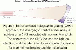
A concave holographic grating (CHG) can be used as an alternative to thin-film filters to perform DWDM multiplexing and demultiplexing. Thin-film filters work well at low-to-moderate channel counts but quickly become a logistical problem at high channel counts. In the CHG approach, the diverging output of a fiber array is incident on a CHG recorded with non-uniform pitch (see Figure 4). The concavity of the CHG acts as a lens to focus the light upon reflection and the pitch introduces angular dispersion for channel multiplexing and demultiplexing. Since the CHG is operated in Littrow, the light reflected by the CHG returns spatially dispersed to the fiber array. This is a parallel multiplexing/ demultiplexing technology similar to AWGs; only one device is needed to process a large number of channels, unlike thin-film filters and fiber Bragg gratings.
The key advantages of the CHG approach are cost, thermal stability, and performance. The CHG can be manufactured easily and inexpensively using a variety of holographic recording and replication technologies. The multiple paths of the interfering beams produced by the CHG's pitch are through free space so the device does not need to be thermally stabilized as is necessary for AWGs. Finally, the insertion loss, bandwidth, and isolation of the CHG multiplexer/demultiplexer are comparable to commercially available AWGs.
Continued development of technologies is necessary to add more functionality and versatility to the all-optical network. These technologies include adaptations of existing technological platforms to new problems, entirely new approaches, and collaboration with suppliers, customers, and other partners. The driving force behind the development of the all-optical network will continue to be technological innovation to continue to introduce new and exciting optical communications products.
Christopher Lin is an optical design engineer and Dr. Simon Cao is chief technology officer and founder of Avanex Corp. (Fremont, CA). They can be reached at their respective e-mails: [email protected] and [email protected].
- S. Cao, "Fiber Optic Dense Wavelength Division Multiplexer with a Phase Differential Method of Wavelength Separation Utilizing a Polarization Beam Splitter and a Nonlinear Inter ferometer," U.S. Patent No. 6,130,971 (2000).
- M. Shirasaki, "Chromatic-Dispersion Compensator Using Virtually Imaged Phased Array," PTL, Vol. 9, No. 12, pp. 1598-1600 (1997).
- E.G. Churin and P. Bayvel, "Design of Free-Space WDM Router Based on Holographic Concave Grating," PTL, Vol. 11, No. 2, pp. 221-223 (1999).
