Overview of dynamic gain-flattening technologies
All-fiber acousto-optic tunable-filter technology provides significant advantages in insertion loss, spectral continuity, wavelength, and attenuation control.
KIRK FLATOW, DR. HONGTAO HOU, and DR. WAYNE SORIN, Novera Optics Inc.
The economics of DWDM systems continue to drive fierce innovation in many key technologies. The number of vendors providing systems in excess of 100 channels, the roster of manufacturers offering OC-192 (10-Gbit/sec) channel bit rates, and the amount of companies discussing plans for OC-768 (40-Gbit/sec) bit rates are all rapidly increasing. These developments dramatically expand the capacity of optical transport systems.
However, sophisticated equipment comes at a price. The cost of optical-electrical-optical (OEO) signal regeneration in long-haul optical transport systems tends to scale with channel count and line rate. High regeneration cost leads system designers to increase the distances over which an optical signal can be transported without electrical regeneration.
Increasing distance is a complex task. For example, optical amplifiers (OAs)-heralded as the key to repeaterless transmission-create difficult challenges that may limit system performance. Although OAs provide a broad spectrum of gain, their gain shapes, which change as a function of absolute gain level, are not perfectly flat. Control of gain shapes using filters with fixed spectral attenuation profiles is effective only for fixed gain and potentially introduces ripple into gain shapes. As a result, some DWDM channels will be amplified more or less than others, depending on channel position and gain ripple of the amplifier. The accumulation of gain variations over a cascade of amplifiers causes substantial differences in signal levels at the end of the span.
In addition, erbium-doped fiber amplifiers (EDFAs) introduce amplified spontaneous emission (ASE) noise that is amplified in subsequent EDFAs in the network. ASE noise, combined with gain variations, degrades the optical signal-to-noise ratio (OSNR) for certain channels, further limiting system performance. As signal levels degrade and noise increases, bit-error rates also increase, leading to a possible interruption of data traffic.
The OSNR penalty for weak channels is not the only undesirable result of gain non-uniformity. Power levels of strong channels continue to grow to reach the nonlinear threshold, limiting the distance between regenerators in optical transport systems. Problems are compounded in modern agile networks, where channel add/drops modify the load placed on fiber spans and OAs. Such load changes affect spectral-hole burning and interchannel Raman amplification, creating spectral variations in end-to-end gain, ultimately degrading system performance.A dynamic gain-flattening filter (DGFF) is a valuable solution to increase the distance between OEO regeneration, while simultaneously increasing channel count and channel bit rate.
Dynamic basicsDynamic gain-flattening permits automatic adjustment of gain shapes at every OA, optimizing OSNR across the transmission band. By inserting a DGFF at mid-stage in an EDFA or hybrid Raman amplifier, gain levels may be tuned for specific span lengths or adjusted for signal power changes caused by aging or temperature effects. The elimination of amplifier gain ripple allows DWDM signals to travel through many more amplifiers, permitting the concatenation of a higher number of fiber spans than previously possible.In contrast to a static gain-flattening filter, a DGFF accommodates variations in gain tilt over time, and the residual gain ripple from one stage of DGFF does not propagate into subsequent stages of amplification. Moreover, use of a DGFF to eliminate gain variations caused by adding and dropping channels facilitates network reconfigurability.
For optimum performance in concert with OAs, a DGFF needs low insertion loss, low polarization-dependent loss (PDL), and low spectral dispersion, since the DGFF is typically inserted in the mid-stage of an amplifier, where the insertion-loss budget is limited. As part of the DWDM transmission system, a DGFF must also meet system requirements. Spectral continuity (continuous versus discrete filter functions over the optical transmission band) is a key issue, because it affects the independence of the DGFF operation relative to the DWDM system channel plan and thus its transparency to reconfiguration of channels in the system. Spectral con tinuity also affects spectral dispersion over the wavelength range.
Several emerging technologies address these challenges, each tailored for different network architectures.
Comparing filters
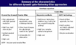
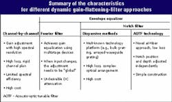
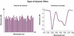
Two general types of dynamic gain equalization (DGE) filters exist: channel-by-channel and continuous envelope (see Figure 1). As the name implies, channel-by-channel equalizers independently adjust each wavelength channel in the spectrum. The basic scheme of a channel-by-channel equalizer requires demultiplexing DWDM signals into individual channels-imposing the desired attenuation for each channel-and multiplexing the channels back into the DWDM transmission line. Because of their high resolution, channel-by-channel equalizers are well suited for fine-tuning individual signal channel intensity or to account for sharp features in the gain equalization spectra.
Continuous envelope equalizing filters make adjustments based on a smooth, continuous filter function. These filters provide ideal spectral shaping for today's OAs, as the gain profile from an EDFA or Raman OA is essentially smooth, with moderate slope (<2 dB/nm) over the entire wavelength range.
Continuous envelope equalizers preserve the continuity of the spectrum, without introducing significant bandwidth narrowing or spectral dispersion at any point in the continuous spectrum. As such, the envelope dynamic filter is well suited for addressing ripple and shape effects created by cascades of inline amplifiers in optical transmission systems. As an additional benefit, a DGFF with a continuous filter function is independent of the channel plan in a DWDM system and thus transparent to reconfiguration of channels in the system.
Fourier series vs. notch
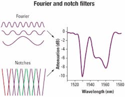
Fourier filters and notch filters are building blocks commonly used to construct envelope gain equalizers (see Figure 2). Fourier methods produce the attenuation profile by superposition of a series of sinusoidal transmission functions, each having different amplitudes and periods. In the case of notch filters, the spectral profile is achieved by adding the correct attenuation in the desired wavelength band.
The Fourier method takes advantage of the fact that the spectral transmission function of a Mach-Zehnder device is sinusoidal. In such a device, light is split into two different optical paths before it is recombined into the output.
The time delay between two optical paths sets the period and phase, and the splitting ratio of the power determines sinusoidal amplitude. Tunability of delays and splitting ratio is achieved using electric-current-controlled Faraday rotators, voltage-controlled liquid crystals, or thermal heating of optical waveguides.
Mathematically, it is possible to produce virtually any profile by expanding its function form into an infinite number of sinusoidal base sets. In practice, due to engineering constraints, only a finite number of Fourier components can be used. Recent studies indicate that Fourier expansion up to the fifth or sixth order produces a reasonable fit to the desired profile in the C-band, with peak-to-peak error of <1 dB. In addition, a sinusoidal filter function introduces attenuation over the entire wavelength range, leading to an undesired DC attenuation level that depends on the target filter shape.
The method of using Fourier series takes a "global" view of the spectrum and expands the spectral profile over the entire wavelength range. Therefore, when the input spectrum changes, or when wavelength range increases, all basic functions must be adjusted globally. That results in changes across the whole spectrum, even if the majority of the spectral profile requires no correction.
In contrast, methods using notch filters take a more "local" approach, attenuating optical spectrum in smaller bands, without disturbing other parts of the spectrum. This approach allows gain equalization of new channels without affecting existing channels.
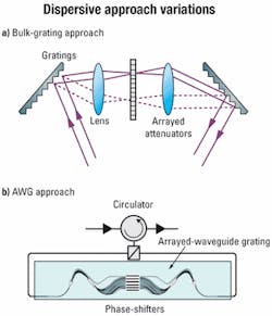
Notch filters can be based on dispersive or nondispersive methods. With the dispersive approach, broadband optical signals are spatially dispersed into sub-bands, and each band is attenuated selectively to produce the target profile. With the nondispersive approach, optical signals at selected wavelengths are scattered out of the optical path to achieve the desired attenuation.
Dispersive approachA well-known methodology, the dispersive approach produces a set of notches with fixed bandwidth and wavelength and attenuation is individually controlled. There are several variations to this approach. Figure 3a shows the use of a bulk grating to achieve wavelength dispersion. The attenuation array can be built of liquid-crystal cells, requiring decomposing light into separately polarized components. Figure 3b illustrates a variation based on arrayed-waveguide-grating (AWG) technology. Light is split into polarization components and sent through the AWG. Dispersed bands are attenuated thereafter via interference induced by thermal phase-shifters.When using dispersive methods, DGFFs tend to exhibit high excess loss (~5 dB), which is undesirable in many mid-stage EDFA applications. Performance, manufacturability, and therefore cost may be affected due to the challenges of aligning gratings or coupling light between an AWG and fibers. DGFFs based on dispersive methods may not scale cost-effectively, since the multiplexer/demultiplexer pair is designed to work within a certain wavelength range and channel plan.
Novel approach
All-fiber acousto-optic tunable filter (AOTF) technology recently emerged as an innovative method for producing tunable notch filters. In contrast to a dispersive approach, all-fiber acousto-optic technology selectively attenuates a wavelength without demultiplexing the input light. A key differentiator of this approach is that wavelength-selective attenuation occurs in the fiber, leading to a significant advantage in insertion loss and spectral continuity. In addition, both wavelength and attenuation can be independently controlled, permitting great flexibility in tailoring filter shapes with a nominal set of notches.
Figure 4 illustrates the operation of an all-fiber acousto-optic tunable notch filter. A continuous singlemode optical fiber is threaded through and attached to an acoustic transducer and concentrator. The AC voltage source drives the acoustic transducer, while an acoustic concentrator focuses acoustic energy onto singlemode fiber. Both the acoustic wave and optical signal are guided along the fiber.
The acoustic wave acts as a long-period grating, coupling a narrow band of light from the guided core mode to one or more cladding modes. By careful design of the interaction length, this band of light is unable to return to the fiber core and eventually stripped away.
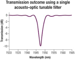
Figure 5 provides an example of the transmission outcome using a single AOTF. The narrow band of light, coupled out of the core, results in a notch in the optical spectrum. The depth of this notch is tunable, depending on the voltage applied.An additional valuable characteristic of the AOTF is that the position of the notch is also tunable, allowing the notch to be positioned effectively anywhere within the operating range of the singlemode fiber. Applied acoustic frequency sets the position of the center of the notch. If the acoustic signal is turned off, or power is lost, the notch disappears. The AOTF reverts back to a standard section of singlemode fiber, with effectively no loss or spectral filtering. That ensures benign behavior in the event of power failure.
Multiple notches, implemented either by concatenating several AOTF assemblies or applying multiple electrical frequencies to a single acoustic transducer, are used to achieve spectral shapes necessary to filter an EDFA gain spectrum.
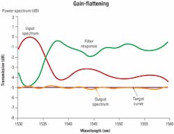
Due to a negligible insertion loss per AOTF, no loss penalty results for concatenating many AOTFs to achieve a desired composite filter shape or resolution. The control of each notch is independent, and the resultant transfer function is the product of individual filter shapes. A multinotch filter, created by splicing together additional AOTFs, has small incremental insertion loss due to splices. Very low insertion loss is a valuable and attractive characteristic of all-fiber acousto-optic technology.Figure 6 shows an example of gain-flattening (using eight independent notches) and the resultant filter shape. The input spectrum represents a typical ASE light source. Spectral equalization reduces typical EDFA gain variation to a peak-to-peak value of <±0.5 dB.
The optical response time of an AOTF is very fast, approximately 40 microsec, or 10 to 100 times faster than comparable technologies. This response time is much faster than today's monitor technology. Although fast filter response is not vital in current point-to-point networks, speed will become an important issue in future agile networks incorporating all-optical switches. Implementation of optical switches will lead to rapid changes in channel loading and result in significant differences in signal intensity among the remaining channels.
The ability to accommodate rapid changes will require close control of DGE, relative to the action of the optical switches. At that point, speed in the gain equalizer must compare to the optical-switch speed to prevent an adverse impact on network traffic. It is expected that the fast response time of the AOTF will be very important in switching applications.
In addition, the construction of the AOTF device does not require complex optical alignment or exotic materials.
Value and performance
The market has recognized the need for DGE, although detailed implementation and the technology platform are subject to extensive evaluation. As products grow into maturity, technical merits, manufacturability, and cost are among aspects under critical examination by network designers. While innovations are taking place rapidly and more technologies emerge, it is clear that the ultimate winners will be those delivering the value and performance required by next-generation, agile, high-bandwidth networks.
Kirk Flatow is formerly president and CEO, Dr. Hongtao Hou is product marketing director, and Dr. Wayne Sorin is chief scientist at Novera Optics Inc. (San Jose, CA).
LIGHTWAVE Editorial Mission
Lightwave is a monthly international publication focusing on fiber optics and optoelectronics, the technologies driving the growth, convergence, and improved performance of telephony, computer communications, and video. Lightwave provides technology news as well as applications and product information for corporate and technical managers and staff engineers. Lightwave's editors emphasize analysis and interpretation in their reports on the technological impact of fiber-optic components, systems, and networks in these markets.
