InGaAs photodiode arrays for DWDM monitoring and receiving
The advantage of using wavelength-division multiplexing (WDM) in fiber-optic transmission systems is clear. It allows orders-of-magnitude increases in the transmission capacity of a system by allowing many carrier wavelengths to share the same optical path and reduces the need for new fiber cable installation. The concept is simple: The signals from multiple laser sources at different wavelengths are combined (multiplexed) at the input of a fiber, then separated (demultiplexed) at the output. Systems using erbium-doped fiber amplifiers (EDFAs) have optical bandwidths on the order of 35 nm in the conventional "C band" (1530 to 1565 nm) and can be further extended into the "L band" near 1600 nm. With channel spacings as narrow as 100 GHz (about 0.8 nm) or 50 GHz (about 0.4 nm), system designers can consider packing over 100 channels into the available bandwidth. These narrow channel spacings give rise to the term dense WDM (DWDM).
Naturally, with these closely spaced channels, the allocated band for each laser source must be narrow, with adequate guardband to prevent interference. Lasers must emit at precise wavelengths and not drift outside of their allocated band. The distributed-feedback (DFB) laser diodes used for high-bandwidth transmission are quantum- well devices. They contain different alloys within the indium gallium arsenide quaternary system grown in layers whose thicknesses can be measured in number of atoms. The emission wavelength of a DFB diode laser depends on the alloy composition, layer thicknesses, and periodicity of the feedback grating. The emission wavelength of the lasers will typically vary by ±200 GHz (±2 nm) over a 50-mm diameter epitaxial wafer. Moreover, the emission wavelength varies with temperature (10 Hz/°C) and drive current (1 GHz/mA).
From a system perspective, with so many transmitted channels, it becomes important to monitor the wavelength and power spectra at critical points throughout the network. This monitoring is especially true in networks where wavelengths and power levels may change dynamically. Diode-array spectroscopy provides many benefits that make the technology an ideal choice for such applications.
There are a variety of applications for spectral monitoring in a DWDM system. Monitoring channel wavelengths allows for detection of laser source drift as well as verification that all expected channels such as at an optical add/drop node are present. Power levels from the output of an EDFA can be used to determine the amplifier spectral-gain characteristics and optical signal-to-noise ratio (OSNR). System designers can use this information to trigger alarms or as feedback to dynamically adjust network elements. Embedded transmission equipment applications require a spectrometer that is compact and rugged and can operate in the demanding environments of an optical-fiber system without sacrificing measurement accuracy and speed.
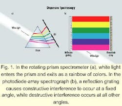
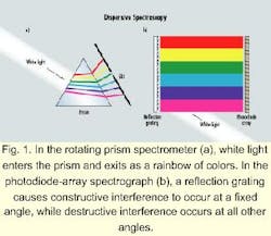
Spectrometers fall into two major categories: interferometric and dispersive. In interferometric spectrometers (such as Michelson and Fabry-Perot), an interference pattern is created from the light source that is related to its wavelength. Most laboratory optical-spectrum analyzers (OSAs), however, are "dispersive"-they incorporate an optical component that "disperses" (spreads) the light source into its individual wavelengths. The original dispersive component was the prism, in which the "dispersion" (wavelength dependence) of the index of refraction causes light of different wavelengths to travel at different angles. White light entering one side of a prism exits the other side as a rainbow of different colors (see Fig. 1a). Use of a slit restricts the exiting light to a narrow band of wavelengths that can be measured with an optical detector. By rotating the prism, different wavelengths exit the slit and a spectrum can be built up one wavelength at a time. The wavelength resolution of a prism-based OSA is fixed by the dispersion of the index of the prism material. Higher resolutions can only be achieved by making the instrument larger, i.e., allowing the wavelengths to spread further.
An alternative to prisms as the dispersive component is the reflection grating. The individual reflecting stripes are grooves either mechanically ruled or formed holographically on a blank. The interference of the reflected light from the different grooves is such that constructive interference for a given wavelength occurs at a fixed angle, while destructive interference occurs at all other angles. The dispersion and wavelength resolution depend on the groove density and the number of grooves. Gratings with 2400 grooves/mm are readily available. In an instrument with a 250-mm focal length and a slit with a 50-micron opening, the wavelength resolution is about 20 GHz (~ 0.15 nm).When dispersive spectrum analyzers were developed in the 19th century, optical detectors were not available. The exit slit was removed and film was used to record the spectrum. As the instrument provided a photograph of a spectrum, it became known as a spectrograph.
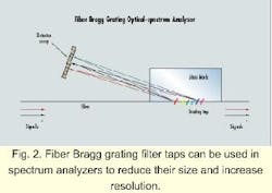
In the 1960s, Solid State Radiation Inc. (later a division of Princeton Applied Research) patented an Optical Multichannel Analyzer, in which the photographic film was replaced by a vidicon tube. During the same time period, Reticon Inc. (later a division of EG&G) developed silicon PMOS photodiode arrays1, and in the late 1970s, Tracor Northern and Princeton Applied Research introduced spectrographs in which the vidicon tube was replaced with a photodiode array (see Fig. 1b). More recently, fiber Bragg grating filter taps2 have been used to reduce the size of the instrument and to increase the wavelength resolution (see Fig. 2).These original instruments were limited by the optical response of silicon in the 250- to 1100-nm wavelength band. Diode-array spectrographs found immediate widespread application. In a single-wavelength spectrometer (dispersive or interferometric), the time to acquire a complete spectrum is the time to move to the next wavelength (or path-length difference), plus the time required to measure the signal with the desired signal to noise-all multiplied by the number of wavelengths in the measured spectrum. In a modern diode-array spectrograph, all the diodes are exposed simultaneously and the measured spectrum is stored on an array of sample-and-hold circuits that allows the next spectrum to be recorded while the previous one is read out. The time required to record a complete spectrum is simply the time required for a single measurement with the desired SNR.
Diode-array spectrographs are found in two important classes of applications. In very-low-light-level applications requiring a minutes-long integration time such as astronomy or Raman spectroscopy, the ability to record the entire spectrum with a single measurement as opposed to hours for single-wavelength techniques makes them the instruments of choice. When more light is available but time is of the essence, diode-array spectroscopy is hard to beat. Rates in excess of 1000 spectra per second are routine, which means that diode-array spectroscopy is ideal for process control and system monitoring.
DWDM system monitoring benefits from all of the key advantages of diode-array spectroscopy:
- The instruments are compact, making use of concave holographic gratings or fiber Bragg grating filter taps to minimize optical components.
- They have no moving parts and are rugged for field use.
- They do not require wavelength calibration in the field.
- With their on-chip signal amplification and integration, they have lower noise than any other photodiode-based technique.
- The single-scan dynamic range is in excess of 40 dB.
- The combination of simultaneous spectral measurements plus the ability to signal-average or add multiple spectra provides the flexibility to trade off between scan rate and dynamic range.
Why are diode-array spectrometers for telecommunications laser measurement just now appearing on the scene? The enabling technology is the photodiode array itself. Indium gallium arsenide (InGaAs) has been the material of choice for single-element telecommunications detectors since the 1980s. This position derives from high sensitivity to the 1300- and 1550-nm fiber-optic wavelength bands, low dark current, and high response bandwidth.
In 1991, Epitaxx Inc. (Princeton, NJ) introduced commercial InGaAs photodiode arrays.3 These pioneering devices were hampered in most applications by an unacceptably high proportion of inoperable pixels (>5%), small optical aperture (100 microns), and nonlinear response due to high dark current and use of a PMOS direct-injection readout integrated circuit.
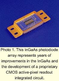
Sensors Unlimited Inc. introduced its first-generation InGaAs photodiode array in 1993, and in early 1998, introduced its third-generation device (see Photo 1). Current devices exhibit dramatically improved performance resulting from improvements in the InGaAs and from the development of a proprietary CMOS active-pixel readout integrated circuit:
- A variety of pixel apertures are available from 50x50 microns for imaging through 50x1000 microns for spectroscopy.
- The baseline device has 256 elements with no inoperable pixels.
- 512-element devices have fewer than five inoperable pixels.
- The CMOS readout integrated circuit contains a high-speed, highly linear capacitive transimpedance circuit in each pixel.
- Large-charge storage capacity (>130x106 electrons/pixel) and on-chip correlated double sampling lead to low noise and high dynamic range (>40-dB OSNR).
- With all clock drivers and analog amplifiers on-chip, the device is extremely easy to use.
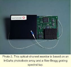
The current design of the Lucent instrument uses a 256-element InGaAs photodiode array to monitor 34 nm with ±0.05-nm wavelength accuracy. Optical power is measured to within ±0.4 dB, including polarization-dependent loss. The fiber input of the device includes a blazed (tilted) fiber Bragg grating that reflects light over a wide band out of the fiber. The device includes optics to disperse and focus the reflected band onto the photodiode array. During assembly, each of the 256 array elements is precisely calibrated for wavelength and power, with performance specified over a range of 70°C.
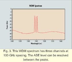
The tradeoffs among bandwidth, accuracy, and resolution can be clearly seen to relate to the number of elements in the photodiode array. Within a 34-nm band, 256 elements correspond to 0.13 nm per element. However, applying curve-fitting algorithms to the raw spectral data effectively increases the resolution and performance, resulting in the ±0.05-nm wavelength accuracy. Consequently, the wavelength and power specifications for the 256-element-based device are sufficient for both 100- and 50-GHz channel-spaced DWDM systems. Within the wide dynamic range of the photodiode array, SNR of greater than 25 dB can be measured for 100-GHz-spaced channels (see Fig. 3). Similar SNR capabilities for 50-GHz spacings can be realized with a 512-element detector array.
By using the InGaAs photodiode array, the Lucent instrument enjoys many of the inherent advantages offered by diode-array spectroscopy without the need for a wavelength reference. With the reflected spectra continually incident on the array, the time to acquire a spectral scan is short (about 50 msec), since a scan only consists of the reading and processing of the data, i.e., no moving parts are required to complete a scan. Concerns about repeatability and long-term reliability are also reduced.WDM and InGaAs diode arrays currently meet only in wavelength monitors, but what does the future have in store?
The photodiode arrays discussed here are essentially hybrid-integrated staring array receivers with an (optical) parallel-in, (electrical) serial-out architecture. While this configuration is appropriate for low-bandwidth monitoring applications, the serial CMOS readout electronics are not suitable (i.e., fast enough) for demultiplexing data. The substitution of parallel output GaAs or silicon trans impedance amplifiers (TIAs) for the serial readout would easily convert the spectrometer system to an integrated SONET-rate WDM receiver. The fiber Bragg grating dispersion and individual diode parameters within the array may be matched to offer full parallel demultiplexing, providing substantial performance, cost, and size advantages over current WDM systems that use multiple drop filters followed by individual InGaAs PIN photodiode/TIA preamplifiers for demultiplexing. Alternatively, a single high-bandwidth TIA used in conjunction with diode-selection field-effect transistors may be used as a field-selectable WDM tuning receiver.
While the GaAs/InP hybrid circuits as discussed above are adequate for current 2.5- and 10-Gbit/sec systems, 40-Gbit/sec systems will likely require full monolithic receiver front ends. The reduced parasitics of a fully monolithic InP-based high-electron-mobility transistor or heterojunction bipolar transistor used in conjunction with a PIN photodiode offer the greatest circuit flexibility and widest bandwidth. There are already reports5 of such single-wavelength receivers, and receiver arrays are sure to be close behind. u
References:
- G.P. Weckler, "Storage mode operation of a phototransistor and its adaptation to integrated arrays for image storage," Electronics, pp. 40, 75 (1967).
- J.L. Wagener, T.A. Strasser, J.R. Pedrazzini, J. DeMarco, and D.J. DiGiovanni, "Fiber grating optical spectrum analyzer tap," ECOC 97 Conference Publication, pp. 448, 65 (1997).
- G.H. Olsen, "InGaAs fills the near-IR detector-array vacuum," Laser Focus World, pp. 27, 21 (1991).
- C. Koeppen, J.L. Wagener, T.A. Strasser, and J. DeMarco, "High resolution fiber grating optical network monitor," NFOEC 98 Technical Digest (1998).
- M. Bitter, R. Bauknecht, W. Hunziker, and H. Melchoir, "Monolithically integrated 40-Gb/s InP/InGaAs PIN/HBT optical receiver module," Proc. 11th Int. Conf. On InP and Related Materials, Davos, Switzerland, pp. 381-384 (1999).
Marshall J. Cohen is executive vice president, J. Christopher Dries is technical liaison of sales and research and development, and Gregory H. Olsen is president at Sensors Unlimited Inc. (Princeton, NJ). Chris Koeppen is a member of the technical staff and Richard Ramsay is product manager at Specialty Fiber Devices, a business unit of Lucent Technologies (Somerset, NJ).
