System tradeoffs in optical-fiber design for long-haul applications
Designed for a minimum of 25 years of life, terrestrial fiber cables will last through several upgrades of the network's transmission equipment. At the same time, today's technology advances demand systems that can rapidly accommodate more wavelengths and higher bit rates. Thus, the fiber design best suited for future upgrades is the one that can handle a wide distribution of wavelengths and their corresponding dispersion values.
Chromatic dispersion (or signal spreading) is one of the most critical parameters in fiber design for today's dense wavelength-division multiplexing (DWDM) systems. In fact, conventional singlemode fiber accumulates dispersion at a typical rate of 17 psec/nm-km. Too much dispersion causes optical pulses to run into each other's time slots, resulting in bit errors. To compensate for this signal spreading, fiber designers have created a dispersion-compensating fiber (DCF) for use periodically throughout a transmission path to squeeze the signal back into shape. This fiber can also be designed to have a negative dispersion slope to compensate both the shorter and longer wavelengths equally in conventional fiber. Unfortunately, DCF typically has high loss. Designers must therefore offset this additional loss by incorporating more optical amplification-an expensive remedy.
While today's generation of nonzero dispersion fiber (NZDF) for long-haul transmission has less dispersion to make up for, designing a "perfectly matched" compensating fiber has proved an elusive endeavor. In general, the problem is the greater the wavelength range, the bigger the compensation problem. When network designers incorporate dispersion-compensating modules to offset the accumulated dispersion at the center wavelength of a DWDM system, the shorter wavelengths are overcompensated and the longer ones are undercompensated. This compensation error can result in severe power penalties and require complex (and expensive) dispersion-compensating solutions. But if the fiber design is flexible enough to achieve a flat dispersion slope (where the dispersion value for the shortest wavelength is roughly equal to the dispersion value for the longest), then the dispersion management for all wavelengths is easily and economically solved.
The second major design hurdle in today's long-haul systems is the optical fiber's nonlinearities-four-wave mixing (FWM), cross-phase modulation (CPM), and self-phase modulation (SPM). Because optical-transmission systems now incorporate higher bit rates and DWDM over longer and longer spans, these nonlinearities can limit system performance. To overcome these limitations and prepare for future system enhancements, fiber designers are attacking the problem in one of two ways:
* They enlarge the effective area so that the power densities are lowered, thus reducing the effect of the nonlinearities.
* They introduce enough chromatic dispersion in the fiber design to counteract the most limiting effects, while reducing the dispersion slope. Reducing the slope also helps control dispersion-management costs.
So why not enlarge the effective area and make the dispersion slope flatter? Unfortunately, there is an inverse relationship between enlarging the effective area and lowering the dispersion slope. The bigger the effective area, the larger the slope gets. While it is possible to do both, these fibers are prohibitively difficult to manufacture and extremely bend-sensitive. Designers must therefore choose to optimize one or the other. So which one should be optimized to get the best results?
The concept here is relatively simple to understand: The effect of nonlinearities is proportional to the power density that the fiber sees. Observe the following formula for the most detrimental of these-FWM: where P(FWM) = FWM power, P = signal power, n2 = nonlinear index of refraction, Aeff = fiber effective area, and D = fiber dispersion.
Basically, FWM is the generation of sideband frequencies that result from the beating of two closely spaced channels. These sidebands interact with other transmission frequencies and cause crosstalk. As shown by the equation, increasing the effective area (Aeff) increases the denominator and lowers the levels of FWM. Suppliers of this technology readily state that the lower power density results in lower levels of FWM. Thus, their fiber designs can achieve longer transmission distances with fewer costly repeaters. How much more power can this design incorporate over smaller-effective-area fibers? By inserting an increase of 30% (the increased amount of effective area for large-effective-area fibers over other fibers) into Aeff, the above formula yields an improvement of 1.2 dB. Some in the industry have claimed that the increase is actually 2 dB, but that would mean the effective area would have to increase 58%.
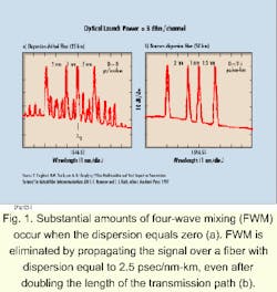
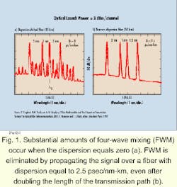
The large-effective-area argument is easy to follow, even with little background in fiber technology. A severe problem with this design strategy, however, is that the advantage of large effective area comes at a price-designers then have to deal with a large dispersion slope. Because of the larger dispersion slope, fibers with large effective area typically have at least 30% smaller minimum dispersion than lower-slope fibers. According to the above equation, this relation can actually result in an increase rather than a decrease in FWM, and thus completely nullifies the potentially higher power-handling capability of large-area fibers.Understanding the advantages of low-dispersion-slope fiber requires some knowledge of the fundamentals of system design. As one can see from the FWM equation, dispersion can suppress nonlinearities. Proper suppression of these nonlinearities is achieved by keeping the minimum dispersion above 2.5 psec/nm-km. FWM is sufficiently suppressed by a small amount of fiber dispersion (see Fig. 1).
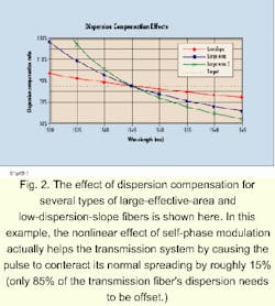
While the suppression of fiber nonlinearities such as FWM is important, an inherent advantage of low-dispersion-slope fiber is that the dispersion values across all the wavelengths used do not become large enough to limit transmission distances. High-slope fibers (such as the typical large-effective-area fiber) will have wide differences between the dispersion found at the shortest wavelengths and those found at the longest wavelengths. Keeping the slope low is essential for economical dispersion management.The effect of dispersion compensation for several types of large-effective-area and low-dispersion-slope fibers is shown in Figure 2. The transmission system considered here incorporates 20 wavelengths across the entire erbium-doped fiber amplifier (EDFA) range (1530- to 1565-nm, 200-GHz spacing). Even after compensating the center wavelength down to the optimal value of 85% (using DCF), there remains some compensation error between the shortest and longest wavelength.
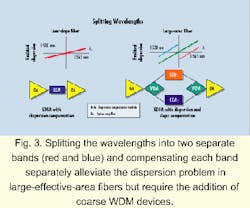
While this deviation is small for fibers incorporating the low slope technology, it becomes detrimental for large-effective-area fiber with high dispersion slope. Since large-effective-area fibers have large differences in dispersion values (high slope), the shorter wavelengths are overcompensated by as much as 70% and the longer wavelengths are undercompensated by as much as 30%. The effect is that the fringe wavelengths (roughly 25% of the total number of wavelengths) will be difficult to use as a viable transmission bit stream. This problem is exacerbated when designers take advantage of the new L-band region between 1565 and 1625 nm.One way to alleviate this dispersion problem with large-effective-area fibers is to split the wavelengths into two separate bands (red and blue) and compensate each band separately (see Fig. 3). While this scheme improves the dispersion management of these fibers, it comes at the expense of a more complex system-the addition of coarse WDM devices-resulting in increased network cost. The coarse WDM devices also require a guardband between the short- and long-wavelength bands, resulting in up to 25% of the wavelengths are sacrificed to make this technique work. Splitting the wavelengths into bands will become even more complex and costly as systems migrate to greater numbers of wavelengths and consequently begin to use the L band of the spectrum.
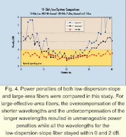
Quantitative analysis of the low-dispersion-slope and large-effective-area fiber technologies through studies that take all potential system impairments into account is one evaluation method. Two examples of this type of comparison are presented.In the first example (see Fig. 4), the study compared the power penalties of both low-dispersion-slope and large-area fibers in a simulated 10-Gbit/sec system supporting 40 wavelengths, with 100-GHz spacing, passing through six 110-km spans. Dispersion compensation was done at each amplifier at the optimum level for each fiber type (85% for low-slope and 90% for large-area fibers).
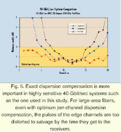
For fibers incorporating large effective area, the overcompensation of the shorter wavelengths and the undercompensation of the longer wavelengths resulted in unmanageable power penalties (above 2 dB). Conversely, all the wavelengths for the low-dispersion-slope fiber remained within the desired 0- to 2-dB region.In the second example (see Fig. 5), a simulated 40-Gbit/sec system was analyzed. In this study, the system comprises 20 channels, with 200-GHz spacing, and has four 80-km spans. Because 40-Gbit/sec systems are 16 times more sensitive to dispersion, more exact compensation is required. A small amount of pre-compensation (about 20%) commercial DCF was used at the transmitter. Then commercial DCF was used at each amplifier to compensate for 96% of the fiber dispersion (40-Gbit/sec transmission is optimum with a different ratio than 10-Gbit/sec). Finally, at the receiver end, each wavelength was individually compensated to correct for the dispersion slope.
This individual compensation was designed to occur after the optical demultiplexer unit module separated all the wavelengths into individual fiber paths and just before the wavelengths reached the receivers. The slope compensation was separately optimized for each of the three fiber types.
By incorporating this slope-compensating technique, all the wavelengths for the low-dispersion-slope fiber were still able to fall below the 2-dB power-penalty threshold. On the other hand, the large-area fiber still had numerous unusable wavelengths, even after compensating for its dispersion slope at the receiver. This situation occurs because nonlinearities will interact with the local dispersion mismatch along the transmission path to cause unrecoverable pulse distortion. For the high-slope, large-area fibers, the pulses of the edge channels are simply too distorted to salvage-even with optimum per-channel dispersion compensation-by the time they get to the receivers.
The analysis presented here clearly shows large-effective-area fibers work best in systems with the following characteristics:
* If the system will only carry a few wavelengths
* If all the wavelengths will use only a narrow portion of the optical-amplifier range (to limit dispersion differences)
* If the 1.2-dB extra span reach will result in significant overall system cost savings (if the system is limited solely by fiber nonlinear effects)
* If the system is not designed for future channel expansion
* If the system is not designed for future upgrades to higher bit rates.
Under these conditions, the dispersion differences between the shortest and longest wavelengths are manageable enough to capture the advantages of lower power densities and the resulting increase in repeater spacing.
Transcontinental submarine systems exhibit many of these characteristics and are ideal for large-area fibers.
Meanwhile, according to this analysis, low-slope fiber works best under the following conditions:
* The designer wants the ability to maximize channel counts.
* The designer is trying to achieve the lowest cost per bit.
* The system will eventually expand into the entire EDFA range.
* The fiber will support even more wavelengths in the L band.
* The fiber will support higher bit rates (40 Gbits/sec).
Fiber designs incorporating low dispersion slope will allow system designers to design transmission systems without complex and overly expensive dispersion-management techniques. At the same time, low-dispersion-slope fiber maximizes wavelength count and provides the best performance at higher bit rates, which ultimately achieves the lowest cost per bit.
Clyde L. Story is technical manager of optical networks at Lucent Technologies (Norcross, GA).
