New generation of amplifiers arrives for optical networking
The first generation of fiber-optic communications systems transmitted light at 1310 nm-the zero-dispersion wavelength of silica fiber. Once singlemode distributed-feedback (DFB) lasers became available, the dispersion restriction became less important than the loss in the fiber. The transmission window for long-haul communications then moved to 1550 nm to take advantage of the lower loss of the fiber in this window.
The advent of the erbium-doped fiber amplifier (EDFA) then made possible systems that transmit signals over thousands of kilometers in the 1550-nm window without regeneration. EDFAs have had a dominant influence on the development of fiber transmission technology, including laser wavelength choice, wavelength-division multiplexing (WDM) schemes, transmission fiber design, and manufacturing techniques. Although the impact of EDFAs on fiber-optic communications systems has been incredibly positive, we are now beginning to run up against the central limitation of this equipment: They generally have a bandwidth of at most 35 nm (1530 to 1565 nm)-the so-called "conventional" or C band. A number of recent developments, such as tight-tolerance DFB lasers, tightly spaced wavelength-division multiplexers/demultiplexers, new fibers such as nonzero dispersion-shifted and dispersion-flattened fiber, all are related to the limited bandwidth of EDFAs in a world with an inexhaustible appetite for bandwidth.
Thus, there is a great impetus to develop EDFAs with greater bandwidth. The introduction of the extended-band (L-band) fiber amplifier last year (see Lightwave, September 1998, page 71) broke the standard EDFA barrier and opened a new window centered on 1590 nm. This new amplifier helps alleviate the problem of WDM transmission in dispersion-shifted fiber, where large-channel crosstalk arises due to zero dispersion and close channel spacing around 1550 nm. It also allows another 80 channels at 50-GHz spacing to be added to the current WDM topology.Hundred-channel WDM systems have been announced and will soon become commercially available. With Internet protocol (IP) over WDM, optical networking, and internetworking, the demands on WDM systems are rapidly changing. How are fiber amplifiers keeping up?
EDFAs started their career in Synchronous Optical Network (SONET) single-channel systems. They were primarily used to extend the reach of optical signals by either replacing and/or avoiding regenerators in existing or planned transmission links. As a result, the requirements for EDFAs depended on no more than two parameters: gain and noise figure. Amplifiers are used to boost the signal power. Thus, the amount of amplification, i.e., signal gain, of an EDFA has to be well characterized during system design to compensate for fiber loss. As an unwanted side effect, amplifiers also add noise to the input signal. The degree of signal-to-noise ratio (SNR) degradation introduced by the amplifier is a key parameter, especially when amplifying weak signals. An amplifier with a noise figure (NF) of 4 dB introduces half the degradation in the SNR of an amplifier with an NF of 7 dB.
As the demand for bandwidth continues to grow, optically amplified WDM technology is rapidly penetrating into both local and interexchange carriers' networks as a very attractive alternative to high-speed time-division multiplexing. Now, each amplifier has to amplify and deal with independent optical signals identified by their specific wavelengths within the gain bandwidth of the active erbium-doped fiber. Since the same gain medium-a piece of erbium fiber-is used not only to extend signal reach but also to compensate for inherent loss associated with splitting and recombining the WDM signals, there are important design considerations to be addressed from a physical point of view. In addition, WDM amplifiers are being required to accomplish more than simple amplification of the signal. An amplifier module for WDM transmission might easily contain components such as dispersion-compensating elements or add/drop multiplexers. The gain of the amplifier is of course still important, but it is not everything.
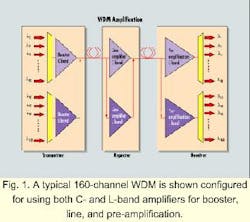
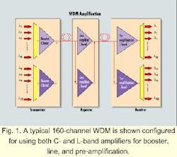
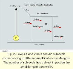
Optical amplifiers are categorized as booster, line, or pre-amplifier to reflect their use in a transmission system (see Fig.1). No matter which category an amplifier falls into, it is essential to recognize that instead of having one signal in the amplifier, as is the case in a SONET system, the same gain medium-the piece of erbium fiber-is shared now by all the WDM channels. These channels are-and have to stay-independent of each other. Yet, the independence of the channels is compromised due to competition among the channels for the limited number of pump photons available in the amplifier.The typical energy transfer scheme inside the erbium fiber is shown in Figure 2. An erbium ion is excited from the ground (low-energy) state to excited level 2 by a pump laser photon (most likely with a wavelength around 980 nm). As level 2 is not stable, the ion quickly relaxes through a nonradiative process to level 3, where it can stay some tens of milliseconds. Now, due to the amorphous nature of the doped silica, the energy of level 3 is different for each ion, depending on its local environment. The ions, however, easily exchange energy thermally, resulting in roughly equal populations in each of these levels.
In a SONET system, all of the signal photons are of one wavelength, resulting in stimulated emission of other photons at that same wavelength. But in a WDM system, each signal consists of photons at a different wavelength. Thus, there is a competition among the channels as to which one will stimulate the most ions down from their excited state, and hence experience the most gain. The winner of the competition is decided by a complex interplay that depends upon the emission cross sections-the probability of stimulating a photon-at the different channel wavelengths, the degree of population inversion, the signal intensities, and the length of the fiber. Optimizing these parameters is difficult, but keeping them optimized under varying signal conditions is the true challenge.
It is obvious that for WDM applications, all channels going through the same amplifier gain medium should have as low an NF and as high a gain as possible. In addition, WDM amplifiers must be designed so the amplifier response for a given channel is not affected significantly by the inputs (power or wavelength) of the other co-propagating channels. Otherwise, if such an interaction exists, the drop or change of one channel would affect the gain and NF of all of the other channels, and the operation of the system will be compromised.
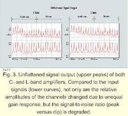
In other words, all channels must be amplified independently and uniformly. As a consequence, in addition to gain and noise figure requirements, WDM amplifiers must also conform to tight specifications with respect to multichannel gain flatness, gain tilt, and channel add/drop response.Gain variation is the first headache for all amplifier designers. The physics of erbium-doped silica dictates that in the competition for stimulated photons, all channels are not equal. Figure 3 shows a typical gain variation for different channels across both conventional and extended-band EDFAs, from 1525 to 1605 nm.
Due to gain variation, the first generation of WDM systems all operated in the red portion of the C band, somewhere between 1540 and 1565 nm. Channel-count increases have forced system designers to put channels into the "trouble area" around 1532 nm, where not only is the NF worse (due to the lower ratio of emission to absorption cross sections), but also the gain variation is much larger than over the rest of the band.
Amazingly, the L band (1565 to 1605 nm) can be separated into two sub-bands in precisely the same way as the C band, with a trouble area corresponding to the amplified spontaneous emission peak around 1570 nm.
Because all signals entering an amplifier will generally be propagating through the same fiber link, it is not difficult to imagine that those signals amplified less will have more trouble reaching their destination without a serious SNR problem. As a consequence, in GR.1312, "Generic Requirements for Optical Fiber Amplifiers," Telcordia Technologies (formerly Bellcore) has specified +1-dB gain variation for all the channels at the amplifier output.
To achieve gain uniformity, passively and actively gain-flattened WDM amplifiers have been launched into the market. A passively gain-flattened WDM amplifier typically uses a gain-flattening filter, which introduces a larger loss to the stronger channels to achieve gain equalization. But due to the attenuation introduced by the gain-flattening filter, more pump power is needed to achieve flatness and acceptable gain levels.
The state-of-the-art gain-flattened WDM amplifier usually does not have a filter at the amplifier output, since having a filter there would cut channel power at a point where a given fractional loss would result in the greatest absolute power loss. For example, a 3-dB loss at the output of an amplifier that has a 40-mW output power results in the loss of 20 mW of potentially useful signal power.
Moving the filter to the input would greatly alleviate this problem. If the gain of this same amplifier is 20 dB, then the input power is only 0.4 mW. Hence, a 3-dB loss at the input would only result in the loss of 0.2 mW of signal power. This minimal loss would greatly reduce the required pump power. But putting the flattening filter at the input is a poor choice for a different reason: A loss at the input adds directly to the amplifier NF-a 3-dB loss at the input gives a 3-dB increase in the NF. Thus, the flattening filter is best placed somewhere in the middle of the amplifier. The placement of the filter in a well-designed amplifier is always a tradeoff between maximizing output power and minimizing the NF.
Passively gain-flattened WDM amplifiers are usually designed for a specific gain requirement-in other words, a well-defined output level for a well- defined input level. They often operate under automatic gain control in the system, meaning that when the input is changed, the output will also be changed proportionally, with the gain remaining fixed.
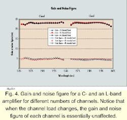
An important feature of the amplifier response is that if the gain of a given channel is clamped, then the gain of all channels will be clamped to a good approximation. This feature fits well in systems where the power level of all channels is fixed but where channels may be added or dropped from an amplified system. As an example, consider a system that originally has 16 channels, with each channel having a -23-dBm power level. When the channels pass through a WDM amplifier with a nominal 23-dB gain, each channel will have 0 dBm at the amplifier output. Thus, the total amplifier output will be 12 dBm.Now, assume that another 16 channels with -23-dBm input power are added to the system. A total of 32 channels pass through the same WDM amplifier. Because the amplifier gain is designed and clamped at 23 dB, each channel will still have 0-dBm output, except that the total amplifier output will now be 15 dBm. To achieve this output, the pump power input into the amplifier will have to be increased. Although more pump power is used in amplifying 32 channels, each channel still gets amplified independently regardless of the presence of other signals. Figure 4 illustrates an example of constant gain profile independent of channel counts.
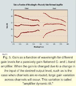
In many situations, the channel-power input into a WDM amplifier is not constant. If channels have to be switched, re-routed, or transported from one point to multiple points, then the channel power arriving at the entrance of a WDM amplifier will never be a constant. If there is to be no degradation in system performance, then all channels must be at approximately the same power level at the WDM amplifier output, independent of the input power. Thus, a WDM amplifier must be able to provide a variable gain, without affecting the amplification uniformity across all channels. Alternatively, there may be situations where the input levels do not change, but we may wish to route the channels along a different path with a larger loss. In such cases, we would wish to have the flexibility of increasing the amplifier gain, again without compromising the gain uniformity.Consider again the above example, but now assume that rather than adding 16 channels, the input power of the existing channels changes from -23 dBm to -20 dBm. If we still want to have 0 dBm for each channel at the output, the amplifier gain must be adjusted to 20 dB instead of keeping it at 23 dB. The problem is that for a passively gain-flattened WDM amplifier, if gain changes, gain shape will also change (see Fig. 5). This is the thorny issue of gain tilt.
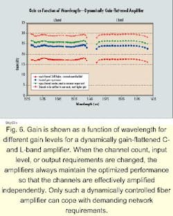
Obviously, a passively gain-flattened amplifier is inadequate in the variable and demanding WDM environment. A WDM amplifier needs to be actively gain-flattened, independent of the gain or the input. That is, it must provide any desired output regardless of the input. The WDM amplifier has to self-adjust, quickly responding to the changing input conditions and gain requirements, which can be achieved through embedded software that calculates the required amplifier configuration and adjusts the amplifier parameters in real time. Software is crucial to WDM amplifier systems, for only through sophisticated software can the various elements in the amplifier be individually controlled.Figure 6 shows an example of tilt-free WDM amplifier performance. In this figure, we plot the gain response of a C-band and L-band amplifier under different conditions. The amplifiers have been optimized for 16 channels with -23-dBm per channel. When the channel number and/or input channel power is changed, the amplifier output remains unchanged. When the required gain is changed, the gain profile remains flat. All of that is achieved through embedded software.
When all channels are the same, WDM amplifier embedded software will generate a control pattern to achieve constant locked gain. When the situation is changed and other gain is required, the software will command the amplifier to generate a different control pattern in order to adjust itself. At the WDM amplifier output, although gain is changed, the response to each channel remains the same, and thus each channel will have the required optical power to continue its propagation.
Equipment manufacturers have recently announced WDM systems with up to 160 channels. The fiber employed is still the same single-transmission fiber. The only change is that more and more channels have to pass through WDM amplifiers. Thus, more and more pumps will be needed to generate enough amplification for the increasing channel counts.
Each pump needs to be monitored for current and temperature. Pump power also needs to be adjusted either to achieve constant gain or tilt-free operation. The control speed is another parameter added to the whole bench, as slow control may result in optical transience during channel add/drop, which saturates receivers and leads to bursts of errors. All of these factors translate into one word: management. One must manage amplifier output variation, gain tilt, response to changing input, and increased number of pump lasers. On top of those, other newly inserted network elements must also be managed, such as dispersion compensators, add/drop filters, switches, and routers. WDM gives optical amplifiers a whole new dimension.
In an optical network, signals are transmitted from a single point to many different points. Bandwidth or capacity is increased by adding amplifiers instead of replacing existing components. Channels are routed through physical layers in a manner analogous to the add/drop points that route the tributaries in the time domain. The ability to dynamically change the points of origin and destination of a channel on a short time scale will be required by all service providers.
Amplifiers designed for optical networking are required to be high-gain, low-noise, and self-adjusting with flat wavelength response regardless of channel count or channel level. WDM systems are becoming more and more complex, with more and more channels and elements. It is thus becoming increasingly important for amplifier designers to work closely with system integrators to ensure that the next generation of amplifiers will meet the stringent requirements of WDM optical networking.
Conversely, system integrators must take the time to understand the subtleties of amplifier design and control in the context of overall system design and control. A black-box approach for the amplifier makes the most sense, especially as this issue likely will have a significant impact on time-to-market for all new amplified WDM product development in the increasingly competitive market for bandwidth.
The new generation of optical amplifiers for amplified WDM systems, optical networking, and IP over fiber do not embody the complexity of a networked system, but they are certainly no longer simply passive gain blocks. u
Dan D. Yang is chief scientist and Marc M. Dignam is a physicist at AFC Technologies Inc. (Hull, QC, Canada). Questions can be directed to [email protected].
