Non-silica-based fiber amplifiers open new wavelength regions for WDM
Wider bandwidth windows will be necessary to increase DWDM channel counts. New rare-earth dopants and non-silica-based fibers offer promising performance in this area.
Optical-fiber amplifiers have revolutionized optical communication systems. They have enabled the exploitation of a much-larger fraction of the intrinsic capacity of optical fibers. Erbium-doped silica-based fiber amplifiers (EDSFAs) have led to the implementation of dense wavelength-division multiplexed (DWDM) systems. A conventional EDSFA provides an approximately 35-nm wavelength region (1530 to 1565 nm) for DWDM signal amplification and allows the realization of optically amplified transmission systems that can carry multiple hundreds of gigabits per second. Yet, transmission systems that employ EDSFAs use only a small part of the intrinsic capacity of optical fiber.
One wants to eventually use the full-spectral width of the fiber. This would yield over 200 nm where the attenuation is less than 0.25 dB/km and almost 400 nm where the attenuation is less than 0.35 dB/km. Implementation of the full spectral DWDM transmission potential will need the use of other types of amplifiers based on other rare-earth dopants and non-silica hosts.
Erbium-doped tellurite-based fiber amplifiers (EDTFA) are promising candidates for expanding the amplification bandwidth of erbium-doped fiber amplifiers. EDTFAs provide an amplification bandwidth of about 90 nm (1530 to 1620 nm). To extend the 1.5-micron transmission band beyond 90 nm, thulium- and praseodymium-doped fluoride-based fiber amplifiers (TDFFAs and PDFFAs) can play important roles. A TDFFA has amplification bands with peak gain wavelength at 1.47 and 1.65 microns, and a PDFFA can realize 1.3-micron amplification operation.
The amplification mechanism of EDTFAs is the same as that of silica-based EDFAs. In terms of optical properties, however, erbium-doped tellurite glass has certain differences when compared to silica glasses. These include high refractive indices of about 2, which result in a larger stimulated emission cross section than conventional silica-based glasses. The crosssection in the 1530 to 1580 nm-wavelength region is larger by a factor of about 1.3 than that in silica-based glass, and it is larger by a factor of more than 2 at about 1600 nm. The longer wavelength limit, which is defined as the intersection of the emission and the excited state absorption crosssection, is 1637 nm. The operational wavelength range of the EDTFA is expected to extend 7 or 9 nm farther into the longer wavelength than the range of the silica- or fluoride-based EDFA.
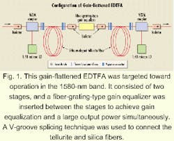
In one experimental EDTFA constructed by NTT, tellurite-based erbium-doped fiber (EDF) was fabricated using the jacketing-drawing method. The preforms and jacketing tube were prepared by suction-casting and rotational-casting methods, respectively. The glass transition temperature was about 400°C. The background loss of the tellurite-based EDF is less than 30 dB/km at 1200 nm.
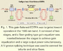
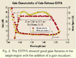
The main difference in EDTFA module assembly is the technology used for splicing the tellurite and silica fiber. A slanted V-groove connection technique was used to achieve low-loss, low-reflection splicing between the fibers. The insertion loss and reflection at the tilted V-groove connection were 0.3 dB and <-50 dB, respectively.Figure 2 shows the gain spectra and noise figure of the EDTFA with and without a GEQ, and the GEQ loss spectrum. We measured the gain characteristics of the EDTFA by sweeping a -30 dBm probe signal over the 1.58-micron gain band while eight WDM signals (1561 to1610 nm, equally spaced at 7 nm) were input at a power of -14 dBm/channel. The EDTFs of the first and second stages were 7 and 5 m long, respectively. The pump powers of the first and second stages were 140 and 217 mW for the EDTFA with and without the GEQ. We achieved a gain of 25.3 dB with a slight gain excursion of 0.6 dB and a noise figure of <6 dB over a broad bandwidth of 50 nm in the 1561- to 1611-nm-wavelength region. The GEQ could exactly equalize the gain spectrum and caused no noticeable increase in the noise figure except at wavelengths below 1561 nm. In addition, we have developed the gain-flattened EDTFA with a bandwidth from 1570 to 1617 nm.
Since the first demonstration of 1.3-micron optical-signal amplification in 1991, the PDFFA has been recognized as a most promising candidate for 1.3-micron system use. One problem that must be overcome before the PDFFA can be practically applied is to find a way of improving its quantum efficiency. A mixed-halide glass and chalcogenide glasses have much higher quantum efficiencies than zirconium-based fluoride glass. There is a question mark, however, about the possibility of using these glasses for praseodymium-doped low-loss fiber fabrication.
Recently, a high-gain coefficient has been achieved using gallium-sodium-sulfide fiber at 1.34 micron; however, its productivity and reliability are still unknown. The quantum efficiency of indium-based fluoride glass is nearly double that of zirconium-based glass. And the glass itself is thermally stable and as durable in terms of humidity as ZrF4-based fluoride glass.Figure 3 shows amplification characteristics of a gain-flattened PDFFA. The amplifier had a two-stage-type configuration with a gain equalizer between the stages. The PDFFA was pumped bidirectionally with two 500-mW laser diode (LD)-pumped Nd:YLF lasers. A flat gain of 28 dB was achieved in the 1290- to 1310-nm-signal wavelength region with a gain flatness of 1 dB. The output power was around 16 dBm for a signal input of -12 dBm.
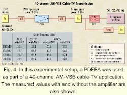
In an experimental setup for 8-channel WDM transmission in singlemode fiber, eight signals were modulated with a 10-Gbit/sec pseudorandom bit stream and were boosted by the PDFFA. The signal-input power launched into each fiber span was set at 6 dBm/channel. The transmission line consisted of 240 km. Two PDFFAs were used as an in-line amplifier. After transmission, the signals were preamplified by a PDFFA. Eight signals were successfully transmitted with power penalties of less than 2 dB.Figure 4 shows an experimental setup for a 40-channel AM-VSB cable-TV transmission experiment. The measured carrier-to-noise ratio (CNR), composite second order (CSO), composite triple-beat distortion (CTB), and composite cross-modulation distortion (XM) values are also indicated. The transmitter was a directly modulated DFB-LD operating at 1307 nm. The input signal power into the PDFFA module was 0 dBm. The output signal power was up to 17 dBm, and the received signal power was 0 dBm. With an optical modulation depth per channel of 7.1%, NTT achieved a CNR of over 51 dB, as well as a CSO of over 65 dB, a CTB of over 65 dB, and an XM of over 60 dB for each signal carrier frequency. Furthermore, the transmitted picture quality monitored on a television set was excellent.
TDFFAs offer a high-gain and low-noise figure in the wide wavelength region of 1450 to 1485 nm with high efficiency of around 10%. They enable long- or medium-distance transmissions since fiber loss is below 0.25 dB/km in that wavelength region. Such amplifiers also enable designers to double or triple the transmission capacity per fiber by using them with 1550-nm-band EDSFAs and 1580-nm-band EDTFAs.
The TDFFA amplification is based on the four-level transition from 3H4 to 3F4 of Tm3+ ions. This amplification is limited by the fact that the lifetime of the upper level, 3H4, is longer than that of the lower level, 3F4, which is a so-called self-terminating system, which prevents us from forming population inversion and achieving efficient amplification.
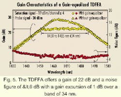
Upconversion pumping and codoping with other ions have been proposed to overcome this problem. Upconversion pumping excites the Tm3+ ions in the lower 3F4 level to the upper 3H4 level through excited state absorption, which depopulates the Tm3+ ions in the 3F4 level and enables population inversion. Compact, high-power lasers at about 1.05 microns, such as LD-pumped Nd:YLF lasers, Nd: YAG lasers, or Yb-fiber lasers, are available for pump sources.Figure 5 shows the gain characteristics of a gain-flattened TDFFA with and without a GEQ employing upconversion pumping. The amplifier consisted of two stages and a GEQ that was inserted between the stages. Each stage contained a TDF that was backward pumped with LD-pumped Nd:YLF lasers. The TDFs in both stages were made of Zr-based fluoride (ZBLAN) glass to achieve efficient amplification, and their cores were doped with 2000 ppm of Tm3+ ions. Their refractive-index difference and cutoff wavelength were 3.7% and 1 mm, respectively. The gain spectra was measured by scanning the gain bandwidth with a -30 dBm probe signal while four WDM signals (1452 to 1482 nm, equally spaced at 10 nm) were input at a power of -19 dBm/channel.
As seen in Figure 5, the amplifier offers a gain of 22 dB and a noise figure (NF) of less than 6 dB with a slight gain excursion of 1 dB over a wideband of 34 nm (in the 1451- to 1485-nm-wavelength region). The pump powers of the first and second stages were 400 and 270 mW for the TDFFA without the GEQ, and 400 and 230 mW with the GEQ. The performance shown in figure 5 confirms that the amplifier provides wide- and flat-gain characteristics, which is beneficial in 1460-nm-band WDM transmission.
The reliability of fluoride-fiber modules should be studied based on two factors. First regards the reliability of the fluoride fiber itself. Practical applications require that a fiber never breaks down, even when coiled around a compact spool in an amplifier module, under any given service condition. The lifetime estimation related to fiber breaking has been calculated.
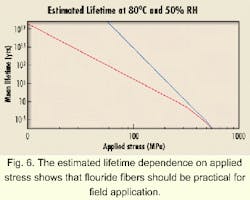
Another factor for the reliability of fluoride-fiber modules is the potential degradation of optical properties (such as splicing loss and return loss at the V-groove splice between fluoride and siliva fiber) due to such environmental conditions as temperature, humidity, mechanical shock, etc. To demonstrate the long-term capability of fiber amplifiers to perform their functions reliably, the Bellcore Generic Requirement GR-1312-CORE ("Generic Requirements for Optical Fiber Amplifiers," Issue 2) is usually used as the qualification test procedures.Lifetime estimation and static-fatigue tests that take zero-stress aging and stress-corrosion effect into account have been carried out. Figure 6 shows the estimated lifetime dependence on applied stress at 80°C and 50% relative humidity (RH). The dashed line indicates the lifetime estimated only from stress corrosion. As the estimated lifetime in a practical stress region of about 100 Mpa is over 25 years, fluoride fiber can be expected to withstand a practical environment. (An applied stress of 47 MPa corresponds to the stress applied by a 75-mm-diameter fiber bobbin.)
We tested the reliability of our fluoride-fiber module with reference to the Bellcore Technical Advisory TA-NWT-001221. This advisory is generally used for ensuring the reliability of passive optical components. Since no appropriate reliability standard has been established for fluoride fiber, we followed this advisory based on the fact that the fluoride-fiber module itself is a passive optical component without pump power. Under this test, we determined that a sample had failed if there was a loss change of more than ±0.2 dB. The tests revealed that the loss changes were small and all the fluoride-fiber modules met the Bellcore criteria.
Qualification tests under high-power pumping is important; however, there is no qualification standard. Therefore, we have started a program to examine long-term stability for 1300-nm signal gain of PDFFAs with 400-mW pumping and 0-dBm input-signal power conditions. Our preliminary results suggest that the fluoride-fiber modules are sufficiently reliable for high power operation.
Makoto Shimizu is the leader of a group at NTT Photonic Laboratories working on optical-fiber amplifiers (Ibaraki, Japan).
