Photon-counting techniques for fiber measurements
Remember the photon? An accurate approach for counting photons can enable instruments with high sensitivity and resolution.
Bruno Huttner and JÜrgen Brendel
Luciol Instruments
Merely 10 years ago, the bandwidth of optical-fiber networks seemed virtually unlimited. An optical fiber was a large pipe that could transmit as much information as needed, as quickly as required. The need for detailed characterization of the network was minimum. If the network allowed the light to go through, it would certainly work well.
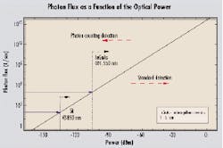
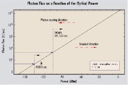
This notion is now history. The "unlimited" bandwidth is now barely enough to cope with the ever-increasing demand. Transmission rates have soared (10 Gbits/sec is becoming a minimum). WDM technology means that the same fiber now needs to carry a whole bunch of different wavelengths, going all the way between 1,510 to 1,580 nm, and more. All-optical systems are replacing electronic repeaters, which enabled the reshaping of the signal.Figure 1. This graph exemplifies the large number of photons corresponding to optical powers commonly used in telecom. Typically below -70 dBm, standard detectors have to be replaced by photon counting. The limitations are given by the dark counts of the detectors. Silicon avalanche photodiodes are usable in the visible region, until about 1,000 nm. They have a dark count rate of 100/sec and can detect signals below -130 dBm. In contrast, indium gallium arsenide photodiodes are sensitive at telecom wavelengths but have a much higher rate of 100,000/sec. They are therefore limited to about -100 dBm.
The fiber may still be totally transparent, but refined knowledge of the transmission network is now required to ensure that the signal will be transmitted faithfully. For example, we need not only the attenuation, but the attenuation as a function of wavelength (see the importance of gain flattening in optical amplifiers). Chromatic dispersion is now a limiting factor. Polarization-mode dispersion and polarization-dependent loss need to be well specified. Return loss of all components has to be known. The message is: You have to characterize your network better and better, with new parameters, which were not even measured until a few years ago.
An adequate analogy is a railway system. The gauge is the same for all trains, including the new bullet trains. However, sending a bullet train at high speed onto the old network is a sure recipe for disaster. The best solution is to use new, specially designed tracks. Standard tracks may also be used, at a reduced speed, provided they are controlled and analyzed properly. The situation is similar with optical networks. Either you use a new, specially designed network, or you rely on the old one, with reduced capabilities. In both cases, the network has to be fully characterized for the new transmission systems. This calls for innovative measurement techniques.
A limiting factor for standard measurements is the sensitivity of the detector. You need to get enough light onto your detector to measure anything. Moreover, the higher the bandwidth of your detection system, the lower the sensitivity, meaning that if you want to measure a signal with high temporal precision, you have to accept a lower sensitivity.
Photon-counting techniques break this sensitivity/bandwidth barrier and provide the highest-possible sensitivity allowed by the laws of physics. However, going to photon-counting detection is not only a technological issue. The changes in the instruments go much deeper. While the output of a standard detector is an analog electrical current, the output of a photon-counting detector is a series of calibrated current pulses. The transition from analog to digital is performed right at the optical level. Further processing can be done by standard logical components, well adapted to modern electronics. This "all-digital" aspect ensures simpler and more robust instruments.
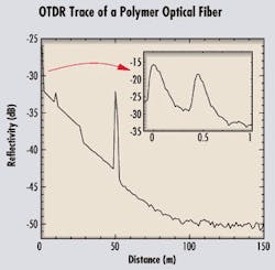
Before we look into some of the technical aspects of photon counting, let's go back to the basics, to the very concept of a photon. This concept was first introduced by Albert Einstein in 1905. To explain the photoelectric effect, whereby light is transformed into an electric current, Einstein introduced the concept of a quantum of light, which later became known as a photon. Light is not like a smooth continuous wave propagating at the surface of the water. Rather, it is more like a hailstorm, with each photon being a single hailstone. This interpretation was a radical departure from the ideas of the time, probably as bold as the theory of relativity. It paved the way for the discovery of quantum mechanics, and much later, to the invention of the laser.Figure 2. The fiber under test is a long polymer optical fiber, with several features. The output connector is followed by a second connector at 45 cm, clearly seen in the inset. At 10 m, there is a fault, induced by a heavy weight on the fiber. A sharp bend at 26 m induces a 1.8-dB loss. A third connector is introduced at 50 m, leading to high reflection. The signal is hidden by noise after 100 m. The attenuation of the fiber is measured at 0.18 dBm. Photon-counting detection enables the use of very short pulses (500 psec) and a high-sensitivity/high-resolution system.
In modern-day optical communications, we use lasers and photodetectors, but we seldom need the concept of the photon. For engineers who design fibers, systems, or instruments, light is a classical electromagnetic field, entirely described by the so-called Maxwell equations (remember those college undergraduate years?). The reason is that to attain the high reliability we need in telecommunications systems, a single bit has to be encoded in a rather intense light pulse, with thousands of photons. In this case, the "grainy" character of the light is not relevant and the classical approximation is sufficient.
To give a feeling for the orders of magnitude, we show the photon flux versus the optical power in Figure 1. A flux of one photon per second at 1,550 nm corresponds to a power of -159 dBm. Perhaps more intuitively, a light beam with a power of 1 mW (or 0 dBm) corresponds to a flux of roughly 1016 photons per second. At this power level, even a short 100-psec pulse contains one million photons. That still leaves us with about 1,000 photons per pulse after 30 dB of attenuation.
The picture changes as the intensity of the light becomes weaker. At a sufficiently low level, even for a continuous input beam, the energy in the beam becomes a series of discrete bursts, each one corresponding to a single photon. Detection of very weak signals therefore requires single-photon counting. That may typically be the case for optical-fiber measurements.
Photon-counting techniques in the visible spectrum are well developed. They are commonly used for the detection of very weak light levels, for example, in astronomy, spectroscopy, and sensors. Photomultiplier tubes (PMT) or silicon (Si) avalanche photodiodes have been specially developed for single-photon counting. At telecommunications wavelengths, detection of single photons is more difficult due to the lower energy of each photon. However, recent work by various research groups has demonstrated that photon counting at telecommunications wavelengths is possible with indium gallium arsenide (InGaAs) avalanche photodiodes.1 This technique can thus be applied to fiber-optic instrumentation.
The common principle of all photodetectors is the photoelectric effect. A photon impinging on a sensitive layer is absorbed, while emitting a charged carrier pair. The current corresponding to one photon, or one carrier pair, is too tiny to be directly measurable. In avalanche photodiodes, each free carrier emitted by the photons is accelerated by a high voltage and emits several new carriers during collisions with surrounding atoms. It is the same principle as in a nuclear reaction, where each particle has enough energy to generate new particles, thus creating an avalanche process.
This nuclear analogy is also useful to understand the two regimes of an avalanche photodiode. If the tension is not too high, the avalanche is controlled, like in a nuclear plant. It is a so-called linear regime, where the number of emitted carriers remains proportional to the number of input photons. Most avalanche photodiodes are used in this regime. However, the gain of the device (below 100) is still too low for single-photon counting.
The second regime, called the Geiger mode, is more like a nuclear bomb. A single photon is like a trigger, using up all the energy stored in the device. In this regime, the gain in the device can reach several thousands, thus generating a macroscopic current that is easily detectable. The problem is that the output current is no longer proportional to the input. One, two, or three photons would give the same current. That's the price to pay for being able to detect one photon at a time.
An extra problem, common to both regimes of avalanche photodiodes, is dead time. During the avalanche process, a macroscopic current flows through the device, which is therefore conducting. That lowers the voltage across. Since the photodiode has a finite capacity, recharging takes some time, during which the photodiode is not sensitive. Typically, this dead time is tens of nanoseconds. Therefore, even though the response time of an avalanche photodiode is as low as 500 psec, it seems it's not possible to measure events with a temporal precision better than tens of nanoseconds.Figure 3. The broadband light-emitting diode is driven by a pulser to emit a 500-psec-long optical pulse. This pulse goes through the coupler to the Bragg gratings, each one reflecting a particular wavelength (Λ1 to Λ5), which generates a series of five pulses, one at each wavelength, separated by delay t. During the propagation through the fiber under test, chromatic dispersion modifies the delay between the pulses, for example, to t'. The time-resolved detection measures this new delay. The difference t'-t is the group delay, from which chromatic dispersion can be inferred. Photon-counting detection is necessary to obtain the high sensitivity and high temporal resolution needed.
Avoiding both problems requires a significant change in the conception of the instrument. This situation is best understood using an example. Let's assume we need to measure the height of a light pulse. In standard detection, we send a single pulse to the detector, which generates a current proportional to the height of the original pulse. To get better precision, it may be necessary to repeat the experiment, sending a series of similar pulses and averaging the results. Suppose now that the intensity of the light is too low, so that we need to resort to photon counting. The intensity of the initial pulse, i.e., the number of photons it contains, does not influence the output. To be able to measure this intensity, we need to attenuate the light beam even further to ensure the average number of photons per pulse is much lower than one. Each time we send a pulse, we may or may not obtain a count. But if we send many pulses, the average number of counts will reflect the input intensity.
We have gone from a single-shot, deterministic measurement, where averages are only used to lower the noise, to a multishot, statistical one. By doing so, we have recovered linearity, together with the high sensitivity allowed by photon counting. Further, we have cancelled the effect of dead time. Since each pulse leads to at most one detection event, the dead time of the photodiode has no influence anymore.
A significant added advantage is the transition from an analog measurement (the output varies continuously as a function of the input) to a digital system (discrete counts). Each detected photon generates the same current pulse. The only remaining task is to count the number of pulses. As is well known from the electronics world, digital measurements are much more robust and easier to process than analog ones, because, for example, they are less sensitive to noise. An instrument based on photon counting can thus be simpler and more robust than its counterpart, based on standard detection.
As explained previously, photon-counting techniques are useful in all instances where the intensity of the detected light is too low for standard detection. The simplest and most obvious application is therefore for high-sensitivity power meters. A typical regime would be for a power range below -70 dBm, where standard instruments fail. The lowest measurable power depends on the precise characteristics of the photodiodes and especially the noise. At telecommunications wavelengths around 1,550 nm, this power can reach -100 dBm. This limit is even lowered at shorter wavelengths where low-noise detectors are available (see Figure 1).
In other cases, the overall intensity of the light may be high enough for standard detection, but it may be necessary to split the power into several channels. If the power per channel is too low, it's again best to resort to photon counting. That may occur, for example, for a high-precision wavelength measurement by means of an optical spectrum analyzer (OSA). The principle of all types of OSAs is similar. The light beam is sent toward a dispersive element, which separates the different wavelengths. This element can be a prism, grating, or filter, according to the resolution required. For high resolution, you need to have very small wavelength "bins," which may contain only a few photons each. Here again, photon-counting techniques may be used to get higher sensitivity.
Another instance where the measured intensity may be critical is the optical time-domain reflectometer (OTDR). The principle of the OTDR is well known. A short pulse of light is sent trough the fiber under test. Any reflective event in the fiber sends some light back toward a detector. Precise measurement of the arrival time of the light gives the position of the event.
In addition, due to microscopic inhomogeneities in the fiber, there is a continuous background of backscattered light-the Rayleigh backscattering (RBS). Measuring the intensity of the RBS as a function of the distance gives the attenuation of the fiber. Here, in order to get a high spatial resolution of the events, you need both very short pulses and precise timing. Time is discretized in small bins, and the intensity of light received in each bin is measured. The higher the precision required, the smaller the bins. Therefore, even though the input pulse is rather strong, the number of received photons in each bin may become very small. That's why even standard OTDRs require avalanche photodiodes for the detection.
Photon-counting techniques enable the use of sub-nanosecond pulses, leading to a spatial resolution in the centimeter range. An OTDR trace of a step-index polymer optical fiber (POF) is shown in Figure 2, where several features can be seen: the input connector; a damage in the fiber at 10 m, leading to a reflection; a sharp bend at 26 m, leading to a 1.8-dB loss; and a connector at 50 m. Note that the width of the reflection at the connector is about 0.6 m, much higher than the expected resolution. That's due to the high modal dispersion of the step-index POF, which spreads the 500-psec pulse to about 6 nsec after propagation through the 50-m fiber. The true resolution of the instrument is shown in the inset-a zoom of the first meter of the fiber. The first peak is the output connector, and the second peak is an extra connector at 45 cm.
In some sense, chromatic-dispersion analysis combines the above two measurements. To measure chromatic dispersion, you need high precision on wavelength and a high temporal precision all at the same time. An example of a photon-counting chromatic-dispersion analyzer is demonstrated in Figure 3. A short LED pulse (500 psec), with broad spectrum, is sent through a coupler toward a series of Bragg gratings. Each grating reflects one particular wavelength toward the coupler. The output of the emitter is thus a series of pulses, precisely timed, at different wavelengths. These pulses are sent toward the fiber under test. Chromatic dispersion modifies the distance between the pulses at the analyzer. Measuring the time of arrival of these pulses gives the group delay and therefore the chromatic dispersion.
Here, we use the full power of photon counting: high sensitivity combined with good timing resolution. The advantages of this technology, in addition to the simplicity emphasized in Figure 3, are the speed and high dynamic range. Indeed, a full measurement only takes several seconds, and the dynamic range is 35 dB over the full wavelength range of the LED.
We have only shown the very basics of photon-counting techniques, directly usable for fiber measurements. The main advantages of photon counting are high sensitivity combined with high temporal resolution. Moreover, the "all-digital" technology associated with this technique ensures simple and robust instruments.
In addition to these immediate possibilities, photon-counting technology may open up a whole new bottle, which includes all the applications of quantum effects. Once you have a way of detecting single photons, you can look at all the new possibilities brought about by quantum mechanics.2 One very interesting example not too far from industrialization is quantum cryptography, which uses the properties of single quanta to encode information with guaranteed secrecy. Another one, still very speculative though, is the quantum computer, which could execute certain tasks exponentially faster than its classical counterpart. But even for a field evolving as fast as telecommunications, this application is for the future.
- A. Karlsson, M. Bourennane, G. Ribordy, H. Zbinden, J. Brendel, J. Rarity, and P. Tapster, "A single-photon counter for long-haul telecom," IEEE Circuits & Devices, November 1999, p. 34.
- H-K. Lo, S. Popescu, and T. Spiller Eds., "Introduction to quantum computation and information," World Scientific (Singapore, 1998).
Bruno Huttner and JÜrgen Brendel are co-founders of Luciol Instruments, a Swiss startup specializing in fiber-optic instrumentation using the photon-counting technology. They can be reached at [email protected].


