New technology for tunable dispersion compensation
A system demonstration of a chromatic-dispersion compensator based on photonic processing technology shows promising results.
CHARLES MAO, CHARLENE YANG, and SIMON CAO, Avanex, LARA GARRETT, MICHAEL EISELT, ALAN GNAUCK, and ROBERT TKACH, AT&T Labs
Tunable dispersion compensation will be a valuable tool in optical-network design as dense wavelength-division multiplexing (DWDM)-based networks continue to increase in capacity and length, fueled by the explosive growth of the Internet. DWDM technology trends focus on channel data rates of 10 Gbits/sec or higher for terabit network capacity, smaller channel spacing for increased channel count, and extended optical distance for improved optical networking with reduced system cost. In all scenarios, the chromatic-dispersion effect in optical fibers is one of the major performance bottlenecks.
Tunable dispersion compensation can extend transmission distances, mitigate nonlinear effects, and improve system margins. Tunable compensation will be necessary in optical network design as the dispersion limit continues to decrease quadratically with data rates increasing from OC-48 (2.5 Gbits/sec, ~1,000-km singlemode fiber-SMF) to OC-192 (10 Gbits/sec, ~64-km SMF), and OC-768 (40 Gbits/sec, ~4-km SMF). Tunable compensation can also reduce the need to carefully measure every fiber span in the installed network, where the actual span lengths vary on a per-span basis. Furthermore, very-fast or very-long WDM systems can require dynamically tunable compensation to allow for environmental changes.
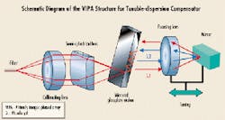
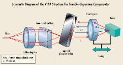
The two most established optical-processing techniques for dispersion compensation are dispersion-compensating fiber (DCF) and chirped fiber gratings (CFG). DCF, the only solution currently deployed in real systems, is a specially designed fiber with very large negative dispersion that is not tunable. DCF has high fiber attenuation and bending loss and thus requires additional optical amplification. Also, the DCF modules occupy substantial shelf space that is very valuable in today's central offices. The fiber design required to produce the large negative dispersion also produces a small optical-mode diameter and thus higher optical-power density in the fiber core, which leads to a large fiber nonlinearity coefficient that restricts optical system design.Figure 1. Light from a singlemode fiber is collimated through a lens and line-focused into a glass plate with a semi-cylindrical lens. After multiple reflections in the glass plate, the output beams interfere to form a collimated light at a wavelength-dependent angle. In combination with different designs of the reflection mirror and the focal length, the amount of dispersion and the dispersion slope can be tuned by changing distance between the focusing lens and the glass plate.
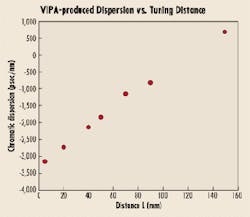
The CFG technology for dispersion compensation provides low-loss, low-nonlinearity compensation that can be tuned by several methods, including temperature and strain. The major limitations of the CFG technology are limited optical bandwidth and signal distortion from wavelength-dependent time-delay "ripple."Figure 2. Large chromatic-dispersion tuning versus tuning distance for a device that can be tuned from -3,160 psec/nm to +660 psec/nm.
A new method of chromatic-dispersion compensation using the virtually imaged phased array (VIPA)1 can be used to realize a dispersion-compensation device that is both tunable and wideband. The VIPA structure is shown in Figure 1. The input light from an SMF is collimated through a lens and line-focused into a glass plate with a semi-cylindrical lens. The left side of the glass plate has a 100% reflection coating except over a small window where the light enters, which has an antireflection coating. The right side of the glass plate has a high-reflection coating so that a small amount of light is coupled out of the plate at each reflection. After multiple reflections in the glass plate, these multiple output beams interfere to form a collimated light at a wavelength-dependent angle. The focusing lens-mirror combination reflects the collimated light back to the glass plate at an angle. This angle depends on the shape of the reflection mirror and the incident angle of the collimated beam. The beam returning to the glass plate at a different position will yield wavelength-dependent time delay when the light is coupled back into the output fiber. In combination with different designs of the reflection mirror and the focal length, the amount of dispersion and the dispersion slope can be tuned by changing distance between the focusing lens and the glass plate. Figure 2 shows the large chromatic-dispersion tuning versus tuning distance for a device that can be tuned from -3,160 psec/nm to +660 psec/nm.Figure 3. Group delay and loss spectrum over one spectral range of a virtually imaged phased-array device at 1,520.9, 1,550.4, and 1,568.8 nm demonstrating broadband performance.
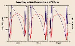
Avanex has fabricated variable dispersion compensators using the VIPA technology. A lab demonstration of a beta unit was conducted at AT&T Research Labs.2 Figure 3 shows the measured group delay and loss characteristics of the VIPA device over one free spectral range at center wavelengths of 1,520.9 nm, 1,550.4 nm, and 1,568.8 nm, demonstrating 70-nm optical bandwidth. The VIPA device was designed for 100-GHz periodicity with center frequencies on the ITU grids. The characteristics such as chromatic dispersion and transmission spectrum are periodic over a broad wavelength range. Because group delay is compensated on a per-channel basis rather than across the entire WDM spectrum, penalties from nonlinear interchannel interactions within the fiber can be reduced as well. The dispersion varies with wavelength across the passband from -1,100 psec/nm to -1,800 psec/nm for this specific module. The insertion loss is 8.8 dB, and the passband 3-dB bandwidth is 0.48 nm. The dimensions of the VIPA module were 22x23x120 mm. The VIPA device was not temperature- or polarization-compensated during the experiment.Figure 4. The performance of the virtually imaged phased-array device and the dispersion-compensating fiber were compared in the WDM transmission of 16 10-Gbit/sec nonreturn-to-zero signals over 6x80 km of conventional fiber using a recirculating loop.
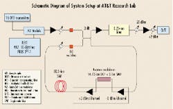
The performance of the VIPA device and DCF were compared in the WDM transmission of 16 10-Gbit/sec nonreturn-to-zero (NRZ) signals over 6x80 km of conventional fiber using a recirculating loop. A schematic of the system experiment is shown in Figure 4. The 16 distributed-feedback (DFB) lasers with channel space of ~100 GHz from 1,548 nm to 1,560 nm are comodulated with a 231-1 pseudo-random bit sequence (PRBS) 10-Gbit/sec NRZ data stream and transmitted into a recirculating loop. The loop contains one 80.5-km span of conventional SMF fiber (17 psec/nm-km) and an inline erbium-doped fiber amplifier (EDFA) with a dispersion compensator inserted in the amplifier midstage. The total SMF span loss is 24 dB, including the recirculating loop switch and coupler, and the dispersion is 1,360 psec/nm. The EDFAs were operated with 3-dBm/channel output power into the SMF and 0-dBm/channel into the dispersion compensation. When tuned for optimal average performance (Q-factor) of channels 1, 9, and 16, the dispersion of both were approximately -1,300 psec/nm. The optimum compensation with DCF was achieved with 14.7 km DCF + 2-km SMF, for a total loss of 12 dB. The VIPA loss, including connectors, was 9 dB.
The performance of all 16 channels was measured after six round-trips through the loop for a total distance of 480 km. The average output optical signal-to-noise ratio (OSNR) in 0.1 nm was 22 dB for both cases.Figure 5. Channel performance measurements after 6x80-km transmission for the virtually imaged phased-array device and the dispersion-compensating fiber.
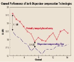
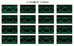
The channel performance for both dispersion-compensation technologies was evaluated with Q-factor analysis from measurement of bit-error-rate (BER) versus decision threshold with -20 dBm received power, with the results shown in Figure 5. The variation in Q with wavelength for each technology is due to accumulated EDFA gain shape. The minimum Q-value is 17.9 dB (2e-15 error rate) for the VIPA case and 17.1 dB (4e-13 error rate) for the DCF case. An improvement in Q relative to DCF is seen for all channels for the VIPA case, with an average improvement of 0.85 dB, indicating some beneficial pulse shaping in the VIPA device. Figure 6 shows eye-diagrams of the 16 channels after six spans for the VIPA case, demonstrating uniform dispersion compensation with very little dependence of eye shape on channel wavelength. There was no dependence of eye shape on input polarization, confirming the low polarization mode dispersion.
We predict that easily tunable dispersion compensation will be a valuable tool in optical-network design as WDM systems continue their rapid increase in channel data rates (from 2.5 Gbits/sec to 40 Gbits/sec) and system lengths (from hundreds to thousands of kilometers). This tunability can be achieved using the VIPA-based dispersion-compensation technology.Figure 6. Eye-diagrams for 16 channels after 6x80-km transmission for virtually imaged phased-array case showing uniform waveform.
The VIPA device is extremely wideband, operating from 1,520 nm to 1,570 nm with a 100-GHz free spectral range. The device has the additional advantages of being physically compact with low nonlinear effects and low polarization dependence. The performance of a beta-unit VIPA device has recently been shown to match that of DCF in a WDM system experiment at AT&T Labs transmitting 16 10-Gbit/sec channels over 480 km of conventional fiber. This experiment was the first system demonstration of the VIPA technology, which is expected to become a valuable technology for future high-data-rate WDM transmission systems.
Charles Mao is director of applications engineering, Charlene Yang is senior engineering manager, and Simon Cao is senior vice president of technology at Avanex Corp. (Fremont, CA). Lara Garrett is a principle technical staff member, Michael Eiselt is principle member technical staff, Alan Gnauck is a technology consultant, and Robert Tkach is division manager at the Lightwave Networks Research Div. of AT&T Labs (Red Bank, NJ).
- M. Shirasaki, "Chromatic-dispersion compensator using virtually imaged phased array," IEEE Phot. Tech. Lett., Vol.9, No.12, December 1997.
- L.D. Garrett, A.H. Gnauck, M.H. Eiselt, R.W. Tkach, Charlene Yang, Charles Mao, and Simon Cao, "Demonstration of Virtual Phased-Array device for tunable dispersion compensation in 16 x 10 Gbits/sec WDM transmission over 480-km standard fiber," Optical Fiber Communication Conference 2000, paper PD7.
