New measurement method a match for DWDM component challenges
Real-time, high-resolution wavelength characterization performed by swept-wavelength tunable lasers looks promising for DWDM components.
Wavelength-division multiplexing (WDM) systems have revolutionized tele communications by enabling tremendous growth in fiber-optic network capacity. Increasing the number of wavelengths supported by WDM systems allows carriers to leverage more capacity per fiber, which is done by decreasing the spacing between channels or by extending the wavelength range.
As the number of WDM channels grows, so too does the complexity and duration of the measurements required to characterize the components used in WDM systems. Components such as isolators, taps, gain-flattening filters, and wavelength-division multiplexers and demultiplexers must be tested for isolation and insertion loss as well as polarization-dependent loss, return loss, polarization-mode dispersion, and chromatic dispersion. With narrower channel spacing, this testing must be done at a higher resolution and over the entire wavelength band. Current state-of-the-art systems, so-called dense-WDM (DWDM) systems, use a channel spacing of 0.4 nm or 50 GHz. Moreover, while original WDM systems were limited to a wavelength range from 1530 to 1565 nm using erbium fiber as the amplifier, new long- (L-) band erbium amplifiers allow today's systems to operate in a 1530- to 1615-nm window.
As component demand increases, the time it takes to perform wavelength characterization becomes a major issue. Typically, a broadband source and an optical spectrum analyzer (OSA) are used to monitor the component performance during the manufacturing process. This method covers a wide wavelength range and scans can be performed very quickly. The tight channel spacing of DWDM systems is straining the resolution limit of these devices, however.
For higher resolution, a tunable laser and detector are used, but this method is limited to the final testing of components because stepping the laser across the wavelength range for a multiplexer can take 20 minutes.
A new measurement method using a swept-wavelength laser source is faster than an OSA and provides the higher resolution required by DWDM components. While this method has obvious applications in the final testing and quality control of DWDM components [1,2], it also creates an opportunity to improve the manufacture of these devices. For example, many DWDM components are optimized during manufacture to set the center (or channel) wavelength accurately or to minimize insertion loss across the wavelength range. One example is a multiplexer based on either fiber Bragg gratings (FBGs) or coated etalon filters. With the FBG, applying a small stress to the grating sets the device's center wavelength. With a coated etalon filter, the center wavelength is adjusted by tilting the optic slightly. The swept-wavelength laser provides a very high-resolution spectral picture of the DWDM component fast enough to observe changes as the component is being aligned. This real-time, high-resolution data can improve the yield of narrowband WDM components, and the testing speed can increase the throughput.
Precision wavelength characterization is generally accomplished using one of the following methods:
- A broadband source and an OSA.
- A tunable laser and power meter.
- A tunable laser and an OSA.
Each method has its own measurement time, wavelength resolution, absolute wavelength accuracy, power stability, polarization sensitivity, and cost. To make polarization measurements, a polarized source such as the tunable laser must be used. There are advantages and disadvantages to each technique.
First, consider how much spectral information there is to gather. In the case of a 50-GHz DWDM system with 80 channels, wavelength spans of over 35 nm must be characterized. The isolation requirement between channels is over 30 dB-that is, the device loss at 0.4 nm from line center is at least 30 dB. The measurement requires a resolution of 0.01 nm or 10 pm with a dynamic range of at least 30 dB, meaning that a typical measurement has at least 3500 wavelength points. Moreover, for polarization-dependent effects, the four Stokes parameters are measured, and polarization-dependent measurements--at a minimum--take three times longer.
The simplest wavelength characterization method uses a broadband source such as an edge-emitting light-emitting diode (EELED) or the amplified spontaneous emission (ASE) of an erbium fiber amplifier with an OSA (see Fig. 1). The EELED typically has a >50-nm wavelength spread with >-13 dBm of optical power, and it can be polarized. The ASE from an erbium amplifier covers the wavelength range from 1525 to 1565 nm with >12-dBm optical power. Newer L-band amplifiers can reach out to 1620 nm. The ASE output of the amplifier, however, is unpolarized, so polarization-dependent measurements cannot be made without additional elements. Both sources have a short coherence length; therefore, spurious etalon effects from unterminated fiber ends are not a concern.Figure 1 shows general layout of a test system using a broadband light source and an optical spectrum analyzer. A typical measurement consists of first characterizing the source, then inserting the device under test and making another scan. By taking the ratio of the two measurements, this method can be used to measure insertion loss versus wavelength as well as isolation and return loss. Because of the resolution limitations, it is better suited to devices requiring less spectral information such as isolators or taps.
Since this method uses a nonwavelength-selective light source, the OSA acts as a wavelength-selective receiver. The diffraction-grating-based mono chromator in the OSA acts as a narrow-wavelength filter. OSAs cover the wavelength range from 600 to 1700 nm with absolute wavelength accuracy of ±1 nm and resolutions of slightly better than 0.1 nm. The advantage of using an OSA system with a broadband source is that it can scan very quickly-a single scan takes about 1 sec (depending on the resolution). In addition, it covers a very wide wavelength range, and it has a large dynamic range to accurately measure the performance of deep filters.
A typical measurement consists of first characterizing the source, then inserting the device under test (DUT) and making another scan. By taking the ratio of the two measurements, this method can be used to measure insertion loss versus wavelength as well as isolation and return loss. Because of the limitation on the wavelength resolution, this method is ideally suited to devices that have little spectral information such as isolators or taps. Devices that have more intricate wavelength dependencies require more complex methods as discussed below.
Where OSAs have proved particularly useful is in the subcomponent assembly level where a relative measurement is sufficient. The speed of the instrument allows technicians to optimize the alignment of subcomponents used in the device to optimize the performance. However, DWDM components are increasing the resolution needed for these measurements, which can challenge the ability of the OSA to adequately meet user needs.
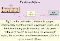
The second common test method uses a tunable optical source, usually an external-cavity diode laser, and a power meter or detector. A tunable laser can scan in 1-pm increments with linewidths of less than 10 MHz. The laser system offers several advantages. It can provide extremely good resolution. It has ample power to multiplex with multiple outputs, and it covers the major wavelength range of interest. Because of the external cavity, the spontaneous emission is suppressed at least 40 dB. But because the power meter is not wavelength selective, it will integrate all the received power over its usable wavelength range. The ASE of the laser, although heavily suppressed by the external cavity, will limit the dynamic range. The dynamic range of most tunable lasers without additional optical filters is in the range of 20 to 25 dB.The laser is stepped incrementally over the desired wavelength region, and the optical throughput is measured with the power meter (see Fig. 2). As it "steps" through the given wavelength region, the laser stops at each measurement point for a given amount of time. Again, a concern is the absolute wavelength accuracy, which is ±0.2 nm when running open loop with most tunable lasers. It is easy to improve the absolute wavelength accuracy with the addition of a wavelength meter. Closed-loop accuracy with the wavemeter can reach <1 pm.
Another easy improvement to the step-and-measure setup is to use a tracking optical filter to eliminate the laser's ASE. For instance, by using a synchronized OSA as a filtered detector the dynamic range can be improved to as much as 80 dB. Of course, this improvement comes with a sacrifice--the total system cost.
The main disadvantage to the step-and-measure technique is the required measurement times. For instance, a broadband device covering the wavelength range from 1520 nm to 1570 nm with 1-nm resolution requires about 50 measurements. With 400 msec as the average step time, this type of scan will take 20 sec. However, a narrowband device like a drop filter will require a 10-pm resolution over 3 nm for 300 measurement points, which will take a few minutes. Finally, with a demultiplexer for a 50-GHz system, performance measurement must include the actual shape as well as the isolation over neighboring channels. The measurement must cover 3500 points, which will take about 20 minutes, and this amount is just for a single output channel of the device.
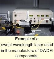
A different technique that can greatly increase production efficiency uses a linearly swept mode-hop-free laser as the source and a high-speed detector as the receiver. In this new method, the tunable laser continuously sweeps over the wavelength range and data is gathered at a moderate bandwidth (<100 kHz). This type of swept-source measurement technique has been used in the radio frequency and microwave community for many years. For example, network analyzers use this combination of a swept source and power meter to characterize insertion loss and return loss in the frequency domain. In the optical regime, the main challenge is in finding a tunable mode-hop-free laser that has a very linear and repeatable scan.Lasers designed specifically for swept-wavelength measurements can combine the resolution of a laser with the speed of an OSA (see photo). The motor design in these lasers ensures very high linearity and repeatability of the scan. Additional features make it easy to trigger detectors at a spectral region of interest to monitor wavelength changes of the component in real time as it is being aligned. Finally, the high output power allows the simultaneous measurement of the multiple output channels in a device. While some companies have recently designed swept systems for final test qualification of components, the capability of real-time, high-resolution measurements in the assembly environment can significantly improve the production of demultiplexers, multiplexers, and other DWDM devices.
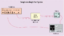
For relative measurements in subcomponent production and assembly, real-time, high-resolution data can be viewed using the equipment shown in Figure 3. In this example, the laser is programmed to sweep over the wavelength range of interest while providing an electrical wavelength trigger. The optical output is sent to the DUT, then to a detector. The output from the detector is displayed on an oscilloscope, triggered using the laser wavelength trigger output. The stability of the wavelength trigger and the repeatability of the laser scan ensure that motion seen on the oscilloscope display is due to the spectral change of the DUT.Figure 3 shows the general layout of a test system that uses a swept-wavelength tunable laser and a detector. The laser is programmed to sweep over the wavelength range of interest while providing an electrical wavelength trigger. The optical output is sent to the device under test (DUT), then to a detector. The output from the detector is displayed on an oscilloscope, triggered using the laser wavelength trigger output. The stability of the wavelength trigger and the repeatability of the laser scan ensure that motion seen on the oscilloscope display is due to the spectral change of the DUT.
A slightly more complicated setup would involve capturing and storing the data, which is done using a data-acquisition card such as National Instruments part number PCI-6110e (5 Mbits/sec, 4 channels) and a general-purpose interface bus (GPIB) controller card such as National Instruments part number PCI-GPIB.
The following examples demonstrate some capabilities of a swept-wavelength laser. The first example involves the measurement of a small temperature drift of a stabilized FBG. The second measurement is similar to how a DWDM using FBGs might be manufactured. It measures the wavelength shift as a small stress is applied to the fiber.
In the first example, the wavelength drift of the FBG must be less than 100 pm in a temperature range from 0° to 60°C for use in a proposed network application. Tunable lasers can provide the resolution needed for this measurement, but the traditional step-and-measure technique is much too slow to monitor the drift in real time as the grating is heated and cooled. OSAs can provide the speed necessary for this measurement but can't meet the resolution requirement.For this test, the programmable wavelength trigger output from the laser was set near the FBG. The electrical timing jitter and the scan repeatability were observed to be better than 5 pm when referenced against an acetylene cell absorption line, which provides an absolute wavelength reference known to be <1 pm. With the laser wavelength scan repeatability demonstrated with this absolute source, the grating's temperature was then adjusted to test the thermal compensation of the component. For the DUT, a total drift of 60 pm was seen over the 0° to 60°C temperature range within the desired specification. Three traces taken at different temperatures are shown in Figure 4. The FBG used for this test had significant cladding modes that showed the temperature drift quite well. With the very high resolution of this technique, additional temperature drift could be observed during the temperature ramp, which yielded information that allowed improvements in the thermal compensation.
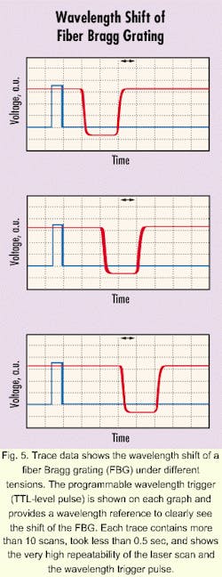
In a second example, the swept-wavelength laser was used to monitor the wavelength of an FBG as the grating was stretched. (This setup is very similar to the one shown in Figure 3.) Three traces with the FBG under different tensions are shown in Figure 5. The programmable wavelength trigger (TTL-level pulse) is shown on each graph and provides a wavelength reference to clearly see the shift of the FBG under different tensions. Each trace contains more than 10 scans and shows the very high repeatability of the laser scan and the wavelength trigger pulse. Each trace took less than 0.5 sec.
With the recent trend toward higher channel counts in WDM systems, the efficiency of wavelength-characterization measurements is becoming a major issue. Although the broadband source and OSA method is fast, it doesn't provide the resolution that is required to fully characterize devices for network systems designers. Techniques based on lasers that step then measure can provide the dynamic range as well as the resolution but are very slow.The swept-wavelength measurement technique combines the speed of an OSA with the high resolution of a laser. While this technique has applications in the area of final test, it also has significant benefits in the assembly of DWDM components and can provide invaluable cost savings as devices grow in complexity. u
- Nyman, Bruce, "DWDM Component Characterization," NIST Symposium on Optical Fiber Measurements (Sept. 1998), p.1.
- Nyman, Bruce, "Four measurement methods characterize WDM components," OptoElectronics World (Sept. 1998), p. S27.
When this article was written, Bob Shine was the laser-product line manager at New Focus Inc. (Santa Clara, CA). He is currently director of marketing at Wave-Splitter Technology Inc. (Fremont, CA). Kathy Li-Dessau is a product manager at New Focus and Steve Cason is a laser-technical sales engineer.


