Long-length fiber Bragg gratings usher in a new era
James F. Brennan III 3M Telecom Systems Division
In less than 20 years, fiber Bragg gratings have evolved from being laboratory curiosities to critical building blocks in the world's communications infrastructure in applications such as dense wavelength-division multiplexing systems and undersea networks. A recent breakthrough in this technology now makes it possible to far exceed the length limitations imposed by traditional grating-fabrication techniques, opening up new opportunities for these devices to operate over extended bandwidth never before possible.
Many advancements have been made in grating technology since 1978, when Ken Hill and his colleagues first observed a photoinduced grating in a germanium-doped optical fiber. Most recently, a new fiber Bragg grating fabrication technique has made chirped long-length fiber Bragg gratings more than 10 m long.1 This technique has made it possible for chirped fiber Bragg gratings of any length to be manufactured by programming that functionality into a computer. This flexible, computer-driven process is a significant shift from the fabrication of conventional fiber Bragg gratings and most importantly lends itself to high-volume manufacturing.
Conventional fabrication techniques have been used to create an impressive collection of Bragg gratings that perform a myriad of functions. However, these fabrication methods have restricted the variability of some fiber Bragg grating inscription parameters. For instance, the length of a grating is limited to the diameter of the laser beam or the length of a phase mask, which can be made practically to a maximum of ~15 cm in length.
Apodization and chirping are also difficult to perform with conventional Bragg grating fabrication methods. Apodization is accomplished by exposing the same length of fiber to two different optical-beam configurations, using specially crafted phase masks or dithering a component of the fabrication system as the grating is written. Chirped gratings are fabricated typically with custom phase masks that have a varying periodicity. To change the parameters of a grating, new optics and phase masks are required, sometimes delaying device development.
In 1995, a Swedish group led by Raoul Stubbe announced that they had fabricated a phase-continuous long-length fiber Bragg grating by stitching smaller gratings together.2 A small grating was written, the fiber was translated by a grating period through a UV-interferogram with a high-precision linear stage, and the fiber was irradiated again. This process was continued until a grating of the desired length was made. With this method, gratings of up to 50 cm in length could be fabricated.
Since this announcement, others have extended this work and fabricated gratings up to 2.5 m long. However, the range of motion of available high-precision staging has limited these fiber Bragg gratings to <~3 m in length.
Numerous applications for long-length gratings have been developed for use in distributed sensor systems, optical pulse stretching and recompression, pattern generation and recognition in code-division multiple-access systems, optical pulse shaping, and nonlinear optical switching. The application most likely to affect the communications industry is the use of long-length gratings in high-bit-rate optical-fiber transmission systems as a chromatic-dispersion compensator.
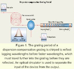
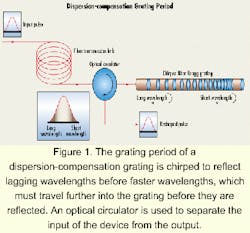
An optical data pulse contains a spectrum of wavelengths. As a pulse travels along a fiber, the shorter-wavelength components travel faster than the longer-wavelength components. This effect, called chromatic dispersion, broadens the pulse to the point that it eventually interferes with neighboring pulses and introduces errors in the detected data stream.
A number of solutions have been proposed for this problem, but dispersion-compensating fiber and chirped fiber gratings are best suited to the task. Dispersion-compensating fiber has high levels of dispersion of opposite sign to that of standard fiber. To compensate for the dispersion introduced by an 80-km span of standard fiber, an ~16-km length of dispersion-compensating fiber would have to be concatenated into the system. These compensation modules are bulky, and due to the fiber design, suffer high optical attenuation and increased optical nonlinear effects. Since no commercially available alternatives exist, dispersion-compensation fiber modules must be used.While longer gratings are optimal, they have not been readily available in the past due to the extreme tolerances that must be maintained in manufacturing quality long-length gratings. Fabrication errors in chirped gratings create ripples in the optical-group delay and thus inaccuracies in the dispersion correction.
System designers have found that these ripples must be <~40 psec peak-to-peak for a dispersion-compensation grating to be useful as dispersion compensators in most systems. This ripple amplitude can be caused by a 20% variation in the Bragg grating UV-induced index change, a ~0.3% dimensional change in a fiber core, or a ~4-pm error in grating pitch. Given that the silicon-oxygen inter-atomic spacing in glass is ~160 pm, many thought holding these tolerances during grating inscription was too difficult, if not possible.
A new fiber Bragg grating fabrication technique has overcome these limitations. As a result, chirped long-length fiber Bragg gratings more than 10 m long have been demonstrated.3 This new process translates a fiber at a precise velocity past a stationary interferogram made with a laser beam that is intensity-modulated at frequency f. In this method, the fiber is treated as the recording medium of an analog signal, analogous to magnetic tape recording, where a magnetic medium is translated at a controlled velocity past a magnetic circuit writing head. The radiation dose F delivered to a fiber along its length x as it is translated at velocity v across the laser beam may be expressed as:
Assuming that the refractive-index perturbation induced in the fiber is proportional to the delivered dose of radiation, a grating of period v/f will be written into the fiber. This result is significant, since a chirped fiber Bragg grating of any length can be manufactured by changing the frequency of the light-amplitude modulation or the velocity of the fiber. This process is flexible, computer-driven, and lends itself well to high-volume manufacturing. A chirped and apodized Bragg grating can be written into the fiber simply by programming that function into the computer that controls the laser-beam modulation.
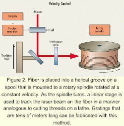
Past approaches have relied on measuring with extreme accuracy the position of a fiber relative to a phase mask to stitch gratings together. But the accuracy of location measurements is limited by the motion stage encoder-usually interferometer-based, which is susceptible to several degradations, such as interpolator inaccuracies, noise in edge-detection electronic circuitry, and random fluctuations in received interpolator-laser light. The advantage of this technique over previous methods is that it is a velocity-controlled approach that does not require position information for feedback and thus is not limited by the throw of available high-precision motion staging. Constant velocity can be maintained to a degree that exceeds available position measurements by appropriately increasing the mechanical inertia of the motion system to mechanically low-pass-filter interpolator errors. This increased accuracy should allow chirped Bragg gratings to be made with decreased dispersion ripple.To meet the accuracy requirement for fabricating quality dispersion-compensation gratings, the fiber must be translated with ~1-ppm (10-6) velocity control, which has been done by placing the fiber into a helical groove on a spool mounted to a rotary spindle (see Figure 2). The spindle is rotated at a constant velocity and a large flywheel is used to regulate the speed. The groove on the spool is like a thread on a screw. As the spindle turns, a linear stage is used to track the laser beam on the fiber in a manner analogous to cutting threads on a lathe. Gratings that are tens of meters long can be fabricated with this method. To meet the tolerances needed to fabricate dispersion-compensation gratings, the spool diameters are trued to a precision of <10 millionths of an inch (250 nm).
Insertion loss dominates the system impact of dispersion-compensating fiber. Likewise, group-delay ripple will likely be the dominant factor for dispersion-compensation gratings.
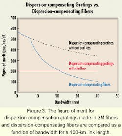
The communications industry has defined a figure of merit for comparing various dispersion-compensation schemes. The conventional figure of merit is defined as the device dispersion normalized by the loss, where the typical value for commercial dispersion-compensating fiber is 200 psec/(nm-dB). This figure of merit does not account for the optical nonlinear interactions in dispersion-compensating fiber or the group-delay ripple in dispersion-compensating gratings. But as an initial metric, it is a reasonable number with which to compare devices.
The length of a grating fixes the total time delay available for dispersion compensation at ~1 nsec per 10 cm of fiber Bragg grating length-the time its takes light to double-pass the fiber length. The dispersion in a fixed length of a fiber Bragg grating determines the bandwidth over which reflection occurs. Longer gratings have more loss and thus an inverse relationship exists between bandwidth and figure of merit. Since practically any dispersion value is possible with a dispersion-compensation grating, the figure of merit of a grating will be dictated largely by the device optical loss which are fixed loss, length-dependent loss, and bandwidth-dependent loss.
Problems associated with fixed loss have primarily been overcome. Fixed loss includes circulator loss and splice losses which should not be larger than ~2 dB. The optical loss at a given wavelength due to absorption and scattering depends on the length in the fiber Bragg grating traversed during the pulse roundtrip. Several mechanisms for this loss have been identified, but others may, and probably do, exist. Likewise, special photosensitive fibers have been used to overcome length-dependent loss. UV-induced losses in 3M photosensitive fibers are ~0.15 dB/m, so the total length-dependant loss will be taken as ~0.3 dB/m, since a given length of grating will be traversed twice. Bandwidth-dependent loss due to cladding mode coupling remains an important area of focus for future research and the next hurdle to be overcome for Bragg gratings to be useful dispersion compensators over wide bandwidths.
When a grating is widely chirped, the cladding-mode coupling produced by a fiber Bragg grating section operating at one wavelength may create loss at another wavelength. This loss will accumulate as a function of fiber Bragg grating bandwidth, typically ~0.3 dB/nm in 3M specialty fibers once the cladding-mode coupling overlaps with the Bragg grating operating bandwidth. The magnitude of this loss is proportional to the square of the strength of the index modulation of the grating, so proper grating designs that include fiber-photosensitivity parameters may reduce this bandwidth-dependant loss considerably.
The figure of merit for dispersion-compensation gratings made in 3M fibers and dispersion-compensating fibers are compared in Figure 3 as a function of bandwidth for a 100-km link length. The fixed loss is taken as 2 dB; length-dependent loss, 0.3 dB/m; and bandwidth-dependent loss, 0.3 dB/nm. The cladding mode loss in 3M fiber begins 7 nm from the Bragg grating initial wavelength as shown. A dispersion-compensation grating has a larger figure of merit than dispersion compensating fiber for bandwidths smaller than ~20 nm. Further developments in specialty fiber designs may reduce cladding-mode losses and extend the bandwidth of these devices. Once this is accomplished, devices will become available that exhibit a figure of merit for dispersion correction higher than dispersion-compensating fiber over a full erbium band.Through advancements in fabrication techniques, it is now possible to produce fiber Bragg gratings for advanced optical networks once considered practically impossible. This flexible fabrication process is computer-driven and applicable to high volume manufacturing.
As a result, products will soon be commercially available. Among the potential applications for new long-length gratings, the one most likely to have an impact on the communications industry is in use in high-bit-rate optical-fiber transmission systems as a chromatic-dispersion compensator.
- K.O. Hill and G. Meltz, J. Lightwave Tech., 15 (8), 1263.
- R. Stubbe, B. Sahlgren, S. Sandgren, and A Asseh, Photosens. & Quadratic Nonlinearity in Glass Waveguides, OSA, 9-11 September 1995, PDP1.
- J. F. Brennan and D. L. LaBrake, BGPP 1999, OSA, ThD2.
James F. Brennan III, Ph.D., is a research specialist for 3M Telecom Systems Division (Austin, TX) where he works on the fabrication of long-length gratings for dispersion compensation.


