Electro-holographic technology as the basis for intelligent lambda switching
Some pieces to the all-optical-network puzzle are still missing; this new technology solution will allow service providers to take wavelength management and discipline to new levels.
Timothy Cahall
Trellis Photonics
The increasing demand for greater bandwidth in public communication networks has spawned a new generation of technology initiatives. Most agree that the future of network capacity lies in the seemingly limitless optical layer.
Unfortunately, the deployment of an all-optical network has been delayed due to the lack of management capabilities of optomechanical switches. This fundamental shortcoming has given rise to optical-electrical-optical switches which, while based on legacy technology, do have usable management features.
Electro-holographic optical switching is an emerging solution that eliminates the need for converting optics to electronics. This technology can support an intelligent lambda-switching solution in an all-optical network that is solid-state, modular, scalable, and flexible and offers inherent monitoring and management capabilities.
Today data and voice networks consist of several physical layers, one of which is the optical layer. This layer is based on a combination of photonic and electronic technology. The electronic components are the limiting factor in bandwidth capacity.
All-optical networks, in contrast, will enable end-to-end data transmission using only optical devices and protocols. An all-optical network can be achieved by transitioning electronics out of the network, which will enable new services and allow network administrators to upgrade to higher transmission speeds without replacing the core optical systems.Optical or photonic switching plays an important role at all levels of switching. From long-haul to metropolitan to interoffice-exchange networks, the challenges remain the same. All-optical networks provide services through wavelength provisioning, protection, and restoration. Service providers running these networks must also structure and meet service-level agreements (SLAs).
SLAs are tricky on two fronts. First of all, if companies are to own wavelengths in a fiber, instead of individual fibers, providers will need to prove that service was delivered as contracted. Unlike the dark-fiber market, demonstrating physical access to the fiber is not sufficient. Accordingly, nonintrusive testing is a key component of the all-optical network. Secondly, wavelengths in a fiber interact. This important feature of an optical-fiber network allows optical amplification, which is an enabler of an all-optical network. However, there is a problem when wavelengths within a fiber interact. For example, a fiber has 160 wavelengths and 120 of those are owned by three major carriers, and the remaining 40 are owned by individual Internet service providers. If one of the wavelengths is saturated with 100 dB of light, all wavelengths within the fiber are disrupted. To realize the full benefits of an all-optical network-in which all of the capacity of a network is used to its fullest-a fast, reliable mechanism for disciplining wavelengths is required.
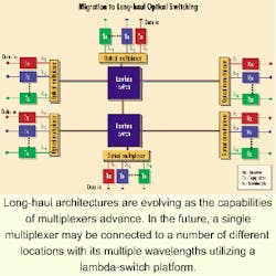
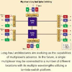
Traditionally, long-distance networks consisted of pairs of transmit and receive multiplexers. These networks had 16 to 40 wavelengths coming off of each multiplexer, with equipment deployed every 300 or 400 miles. Wavelengths were changed from optical to electrical, regenerated, and sent on. The advent of additional capabilities within multiplexing, such as the ability to handle a very high number of wavelengths in a single fiber over extraordinarily long distances, has changed the architecture. Today, manufacturers are working on systems with 3,000, 4,000, and even 5,000 km between multiplexer pairs.
In this environment, a single multiplexer is connected to a number of different locations and its 160 or 320 wavelengths utilize an optical-switch platform. For example, 20 wavelengths will go to Washington, DC, 30 to Atlanta, 40 to Dallas, and so on. Rather than having a multiplexer for each destination, there is a move toward an architecture in which a single multiplexer handles the entire transmission requirement for a location-with optical or lambda switching breaking those requirements down and allowing interconnection with a wide range of sites, each having a similar configuration (see Figure).
An all-optical-switching solution that can meet the requirements of this type of network environment is intelligent lambda switching. At the core of the intelligent lambda-switching solution is a novel technology in optoelectronics called electro-holography (EH), which eliminates the need to convert optics to electronics at each node.
Intelligent lambda switching incorporates EH technology by writing a wavelength-specific hologram, a Bragg grating, into a specially developed potassium lithium tantalate niobate (KLTN) crystal. Each crystal is a mere 2x2x1.5 mm in size. The advantage of a Bragg grating is that it will reflect a specific wavelength of light. For example, if there are three wavelengths (red, green, and yellow) transmitting through a crystal and the Bragg grating is written for the green, then the yellow and red pass through unaffected. Even though the Bragg grating was written for the green, the green passes through the electro-holographic crystal unaffected, as well. When voltage is applied to the crystal, the green is deflected because the Bragg grating within the crystal becomes active. It is therefore an electrically controlled Bragg grating-in the form of a hologram-within a KLTN crystal. That is the basis of electro-holography.
Imagine a pair of crystals, lined up in a column, into which holograms have been written for a specific wavelength, or color, such as red. When neither crystal is energized, the red wavelength passes directly through. If the first crystal is energized, the red is deflected off the first crystal. If the second crystal is energized, the red is deflected off the second crystal. However, a residual amount of red always passes through. The crystal is a non-absorbing material, so the residual light can be used to monitor the light. Finally, the crystal is a dynamic attenuator. When voltage is not present, it is essentially transparent. When full voltage is applied, it is approximately 95% efficient. But when partial voltage is applied-at any chosen level-it is possible to partially apply voltage to the first crystal and send a portion of the beam down the first path; the second crystal can be fully energized and send the residual beam down the second path and create a multicast situation.
Why is this situation important? Real-world implementations of optical switches will entail networks with dozens, if not hundreds, of switches cascaded together. The electro-holographic crystal, switching at approximately 10 nsec, is inherently faster than competing technologies such as micro-electromechanical systems (MEMS), which switch at 15 to 50 microsec, according to these vendors. In that environment, a delay or fault is isolated, recognized by the operations, administration, and maintenance (OA&M) systems, and the whole network must be reconfigured. Once the reconfiguration is selected, all the switches must be signaled, then switched to the new configuration. This process is time-consuming, regardless of the switching fabric employed.
To provide a customer with premium, reliable service, the electro-holographic optical switch can split the beam into two separate but identical pieces at the first point of transmission. The signal then passes through the network on two physically separate, geographically diverse fibers. At the final switch point before the receptor, the primary signal is passed onto the receptor after it is power balanced and equalized; the redundant wavelength is allowed to cascade through the matrix unused. The electro-holographic switch allows for constant monitoring of the residual light from the primary signal. In the event that the primary signal drops below a specific, designated level, the primary beam can be shut off in less than 1 microsec, the appropriate crystal for the redundant signal can be activated, and the second beam can be switched to the receptor. The receptor receives an optically identical signal, power balanced to the same power level as the primary signal-in less than 1 microsec. Once restoration is achieved, the OA&M switch is signaled that something happened. This kind of functionality, inherent to the electro-holographic optical switch, ensures switching reliability by eliminating service disruptions and network downtime.
In electro-holographic technology, the operating wavelength is from the high 900 nm to more than 1,650 nm with no gaps in the spectrum. The data-throughput rate is greater than 100 Gbits/sec. The attenuation of a single crystal with a single hologram is 0.5-dB net attenuation per switching operation and about 0.1% when passed through an "off" switch. That means a wavelength passing through an unenergized crystal has an extremely low loss penalty. With its 10-nsec switching time, the electro-holographic optical switch provides the fastest switching time, with crosstalk better than 40 dB.
At the heart of the electro-holographic optical switch, the crystals are arranged in a matrix of rows and columns, similar to a trellis. The columns represent wavelengths, while the rows represent individual fibers. Crystals are activated within the matrix at the appropriate row and column to direct any wavelength into any fiber. Since the crystal is not an absorptive material, the loss at the point of switching is not due to attenuation of the signal but the slight inefficiency of the Bragg effect. The residual light, that which is not switched, continues through the matrix. This residual is used to power balance and discipline each wavelength.
The ability to power balance and discipline wavelengths is a unique feature of the electro-holographic matrix. Unlike other switching technologies, the electro-holographic switch is wavelength-specific and has the ability to dynamically attenuate each wavelength within the matrix. By monitoring the power of the residual signal, it is possible to ensure that all the wavelengths exiting the matrix into a given fiber are, at the discretion of the user, power balanced to have the same output regardless of the disparities in input power.
In addition to the power-balancing capability, which is the dynamic attenuation feature of the electro-holographic matrix, the optical switch is able to multicast a single wavelength within the matrix. Partially activating a crystal in a column and fully activating another crystal higher in the same column can divide a single beam into two identical parts. This feature is used to enable a premium service allowing extremely fast restoration of a wavelength through an entire network.
Utilizing the same power-balancing and switching speed features as the multicast example, individual wavelengths can be disciplined within the matrix. In the event that any wavelength exceeds its allocated power budget, that wavelength will immediately be attenuated back to its allowed power level. This feature, also unique to electro-holography, enables an operator to ensure that the aberrant behavior of one wavelength in a fiber does not interfere with the other wavelengths.
Finally, the top row of the matrix is reserved for a test row. By activating a crystal in the top row, any or all of the wavelengths in the switch can be brought to a monitoring port. Once attached, the monitoring port can be a local test set, or the signal can be regenerated and carried to a remote monitoring center. Since these signals are optically identical, albeit weaker, than the switched signal, protocol analysis of any kind and at any level can be performed. There is no additional loss or signal noise induced by this function since analysis is performed after the switching function. The test row allows a network operator to monitor every wavelength in every switch in the entire network from a central location. Since the electro-holographic switching fabric has test and monitoring capabilities inherent in the fabric-unlike optomechanical switching fabrics-the need for costly additional test equipment is eliminated.
In short, the electro-holographic optical switch offers dynamic attenuation, power balancing, monitoring capability, the ability to discipline a wavelength, multicasting, and the incredible speed of the electro-holographic matrix. These features make it the only photonic switch capable of serving as the heart of an intelligent lambda-switching solution in an all-optical network.
Where is the simplicity? All of these features are an inherent part of the switching fabric, which provides the nonintrusive testing, wavelength management, and switching speeds that can only be achieved with a solid-state device.
Tim Cahall is the CEO of Trellis Photonics (Columbia, MD).

