Planar splitters are the optimal choice for passive optical networks
Passive optical networks (PONs) require wide wavelength response and benefit in performance from good port uniformity, characteristics that do not go hand-in-hand. Both requirements are met consistently and reliably with planar-waveguide splitters, expanding the futureproof assurance that PON optical access networks provide.
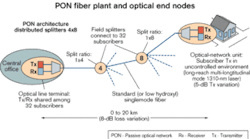
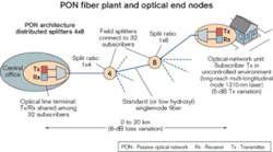
A PON is an access network with no active devices located between the central office (CO) or headend and the subscriber. In the telecommunications access network, cost is the name of the game. The widespread layout of the one-to-many (i.e., CO to all subscribers) architecture requires that maintenance efforts be carried out at any end node in the network. Optical access networks (fiber to the curb, building, and home based on PON) can reduce much of the service issues related to access networks, including repeater node failure and the dependence of line quality on distance from the CO.PON is illustrated in Figure 1. The CO has a bidirectional optical transceiver that sends and receives information to and from 16–64 subscriber nodes, each of which has their own bidirectional transceiver. PON features that reduce operating cost include:
- All network outside plant components located between the CO and subscriber are completely passive, which reduces the cost of powering large cabinets. The absence of electronic current in the node also reduces the chance of node failure.
- The link budget and dynamic range of optical components support full bandwidth operation all the way out to the specified maximum reach.
PON economics demand that the laser at the subscriber's location be the lowest-cost device available that meets system requirements. Where line rates are 1 Gbit/sec or less and distance is up to 20 km, the laser of choice is equivalent to a long-reach multi-logitudinal mode (MLM) 1310-nm laser. The MLM laser wavelength varies by about 0.5 nm/°C.
The utility of placing the subscriber's equipment outside the subscriber's building requires that the laser operate in an ambient environment from –40° to +85°C, resulting in a 125°C variance that can cause the laser to shift wavelength by 60 nm. The manufacturing tolerance of nominal wavelength further adds 40 nm to this wavelength variance. In total, there is a 100-nm wavelength window (1260–1360 nm) to accommodate in the fiber network.
Standard singlemode fiber has two windows of low attenuation: a nominal 1310-nm window and nominal 1550-nm window. The 1310-nm window is what we are considering here. As the subscriber's laser reaches the upper limit of its transmission window (between 1350 and 1360 nm), attenuation begins to increase due to OH- (hydroxyl, a manufacturing containment) ion absorption in the material glass (a.k.a. "water peak" attenuation). The peak wavelength of OH- absorption is 1385 nm. Where the maximum system design wavelength for this window is 1360 nm, a 25-nm guard band exists between transmission wavelength and peak absorption.
Subscribers in an access network can range in distance from 0 to 20 km from the CO. Therefore, the difference in fiber attenuation from one home to another on the same PON can be as much as 8 dB (assuming 0.4 dB/km × 20 km). The tolerance on launch power of the subscriber's laser can be as much as 5 dB. The sum of these results is a potential 13-dB signal power difference between signals received by the CO transceiver, from one subscriber versus another.
Meanwhile, the receiver in the CO can tolerate 15-dB difference between adjacent signals received, leaving only a 2-dB uniformity "budget" to the optical splitter node in a worst case analysis. It is sufficient to note that improved port-to-port uniformity in the splitters used in a PON improves the performance of the network but is not required by network design requirements. Further, the choice of splitter is the only opportunity to differentiate on uniformity performance in the network. Fiber attenuation is a given, and increasing the cost of the subscriber's laser adds cost at the most cost-sensitive point in the network: the subscriber's location.
Fused biconic taper (FBT) optical couplers are manufactured by placing two fibers side-by-side and fusing them together (in the general sense), which makes the core regions draw closer to each other. When light is transmitted down one of the fibers, a fraction of the light is transferred into the adjacent fiber. Light that didn't transfer into the adjacent fiber remains in the original "input" fiber and continues to transmit.
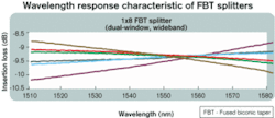
The amount of light split into the two output fibers (e.g., 50% to each fiber) depends on the length of the fused region (longer length creates more light transfer). Light transfer is also wavelength-dependent, so if the desired transfer rate is 50%, then exactly 50% transfer can only happen at a discrete wavelength. While port uniformity over wavelength in FBT-based splitters has improved from the first-generation devices (e.g., creating two exact "50% wavelengths" by flattening the insertion loss curve), the difference of insertion loss between the highest and lowest output port still gets larger since the wavelength is further away from the exact 50% point.Currently, the FBT splitter specifies a premium-grade transmission window of ±40 nm and standard-grade transmission window of ±15 nm. Widening the transmission window only serves to increase the port uniformity in FBT splitters (and consequently maximum insertion loss), as shown in Figure 2. So given a fixed limit for port-to-port uniformity, it is fair to note that production yield for FBT splitters decreases as the transmission window is opened to transport more wavelengths.
In the transmission window from 1260 to 1580 nm, the best description of the wavelength versus insertion loss for a planar-waveguide splitter is that it is "truly flat." The port-to-port uniformity of insertion loss for 1×4 and 1×8 planar splitters is 0.9 and 1 dB, respectively, over a wide operating wavelength range. In a "1×4 and 1×8 distributed architecture," adding the uniformity of these two splitters results in 1.9 dB of uniformity. This 2 dB of uniformity combined with the previously mentioned 13 dB meets 15 dB of differential path loss. More important, the planar splitter specifications referenced here are the result of a standard process, not the result of sorting splitters into different grades of product.
The temperature dependence of a Fabry-Perot laser causes the wavelength to get longer as its temperature increases. As the wavelength increases, the insertion loss experienced at the splitter also changes. Since all lasers on a PON are at most 40 km apart, they all experience the same ambient temperature. Therefore, if one laser's wavelength increases in response to increased daily temperature, then all the other lasers' wavelengths also increase. So the effect is that all lasers move "back and forth" on the insertion loss curve in tandem (see Figure 3).The PON access network is the ideal application for a planar splitter. The wavelength range of performance is continuous from 1260 to 1580 nm. While all these wavelengths are not specified into the PON network, they will be at some point in the 30 years for which this plant will be commissioned. There is a very good reason to install spare fibers into a fiber network: future demand increase. That's the same reason planar splitters are the optimal deployment choice for PON. As shown in the Table, the planar choice is supported from both sides of the equation.
Pete Lee is an application engineer at APA Optics (Blaine, MN). He can be reached at [email protected].


