Measurement range: A new performance specification for otdrs
Measurement range: A new performance specification for otdrs
With measurement range becoming more important to otdr users, here`s a look at how this parameter can be determined.
JOSEF BELLER, Hewlett-Packard GmbH
Ever since Bell Communications Research (Bellcore) presented its first proposal for a measurement range specification for optical time-domain reflectometers (otdrs) in 1993, it has become an important addition to the imperfect dynamic range criterion.
otdrs have evolved into the primary test instrument for the installation, commissioning, and maintenance of optical-fiber networks. During the past decade, dynamic range has often been recognized as the most important otdr performance parameter because it was and still is used to rank an instrument among a specific performance class.
In general, a higher dynamic range is associated with an instrument`s capability to explore longer fiber links, i.gif., to more easily detect events in the fiber`s signature normally buried in noise. This deduction is quite understandable if one relates it to the definition of dynamic range for otdrs. Dynamic range is defined for a given pulsewidth and wavelength as the difference between initial backscatter power level and the noise level; the latter can be either 98% peak noise or root-mean-square (rms) noise level. By means of data filtering, it is possible to reduce the noise level and, therefore, increase the dynamic range at the expense of bandwidth, i.gif., resolution. This is limited by practical considerations because too much filtering leads to smoothed results with unidentifiable details. This way, however, performance characteristics could be claimed that don`t always fulfill the user`s expectations.
To overcome this situation, Bellcore presented a first definition of measurement range with the Generic Requirements for otdr Type Equipment in 1993. A revised version followed in 1995 (gr-196-core). Measurement range deals with the identification of events. It is defined as the maximum attenuation that can be inserted between the otdr and an event for which the otdr is still able to accurately measure the event. Its intention was to propose an unbiased, judicious performance characteristic for otdrs that is strictly oriented to its applications.
Among the event types (splice or component loss, fiber attenuation coefficient, reflective point, broken fiber, or end of fiber), the event loss test at a high loss splice with 0.5-dB insertion loss proves to be the best criterion for assessing an otdr`s basic performance. At first glance, a 0.5-dB loss does not exactly match the loss of a fusion splice that can be well below 0.1 dB; rather, it looks like a figure for mechanical splices. Maybe the idea is that an artificial splice can more easily be reproduced with 0.5-dB insertion loss than with lower figures.
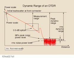
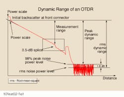
Figure 1 shows, in simplified form, the fiber signature of an otdr measurement. Here, measurement range is always less than dynamic range, and rms dynamic range gives a higher figure than peak dynamic range.
The detection, localization, and determination of an event superimposed by noise is a procedure where the results of repeatedly performed tests show a statistical distribution. That is why the evaluation of measurement range is based on the probability of achieving results with a certain accuracy. With at least four out of five measurements, the insertion loss must be determined with a deviation not exceeding ۪.1 dB. In the Bellcore recommendations, no requirement is given on the accuracy of the splice position. However, precisely determining a splice`s insertion loss with common software algorithms requires the knowledge of the exact event position.
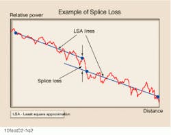
Splice loss is defined as the vertical distance between the two auxiliary lines representing the fiber`s backscatter signal before and after the event (see Fig. 2). The width of the step is, at a first approximation, equal to the width of the probing pulse, but can be broadened by a low otdr receiver bandwidth. It is common practice to apply the least-square-approximation method to determine the slope and position of the two auxiliary lines. More-sophisticated algorithms such as pattern-matching schemes have been developed.
Contributions of measurement range
Superior measurement range offers various benefits to the customer. As a true application-related performance measurement, not only technical otdr parameters such as low noise, loss accuracy, or linearity were stressed. Smart software algorithms also play an important role. An essential feature is that measurement time reduces noticeably due to fast, confident, and reliable results. There is no need to manually check and edit measurement results. Installation and commissioning of cables with multiple fibers means taking lots of measurements repeatedly and intense data management. In such a case any saved time is a bonus.
Also, automatic network supervision depends on reliable data evaluation. False alarms reflect a low-quality monitoring system, especially in security systems. Providers can`t afford this in a competitive environment. Excellent measurement range is an obvious contribution; it is a prerequisite for dependable automatic network supervision.
One of the most frequently asked questions is about the test device. Ideally one would like to have a small, inexpensive device that shows an insertion loss of 0.5 dB at any wavelength of interest. Bellcore proposes that you carefully build a splice of known value or use a 95/5 or 90/10 1 ¥ 2 optical coupler. Only by chance would such a device have a loss of about 0.5 dB in different wavelength windows.
On the other hand, an adjustable splice loss well below 0.5 dB also makes sense, as fusion splices are increasingly replacing mechanical splices. Such a variable splice-loss setup has been developed that offers a splice loss adjustable from 0 to approximately 1 dB at wavelengths from 1200 to 1700 nm.
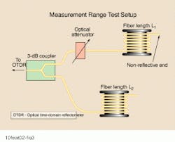
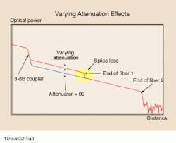
This setup takes advantage of the fact that returning light from different fiber paths overlaps in the otdr measurement result. An ideal attenuator with zero insertion loss would produce a 1.5-dB step at a distance L1. With a finite insertion-loss of the attenuator this step decreases. The higher the added attenuation, the lower the resulting step (see Fig. 4). The end of fiber 1 must be nonreflective, e.g., equipped with an angled connector, for a high-quality splice reproduction. That way, an easy-to-handle and precisely adjustable splice event can be generated for measurement range determination.
The determination of an otdr`s measurement range is a time-consuming, repetitive procedure with many steps. The detection limit is approached by increasing the total loss between the otdr and event. This calls for a computer-controlled optical attenuator to set the total loss. Before the actual measurement, the calibration of splice loss and total loss of the setup can be performed with simple power-loss measurements. This way the initial total loss and the splice loss of 0.5 dB for a given wavelength can be accurately adjusted. Four successful attempts out of five, each with 3-min measurement time, need to be conducted for each total-loss setting to continue the procedure. Once the otdr fails for the first time to accurately identify the splice loss with 80% probability, the present cumulative loss is defined as the otdr`s measurement range.
The table compares measurement range with dynamic range under various aspects. It shows that dynamic range alone doesn`t describe an otdr`s performance class completely. It gives some arguments as to why measurement range is an important complement to dynamic range and why it takes such a long time until measurement range will be fully accepted by the otdr manufacturer and otdr user communities. u
Josef Beller is a project leader at Hewlett-Packard`s Boeblingen Instruments Div. in Germany, where he is involved in research and development of otdrs.Fig. 4. The splice pattern in the center has an insertion loss that can be altered by varying the attenuator in Fig. 3. The splice occurs at the end of fiber 1. Length L1 and L2 should be chosen to form backscatter regions four to five times the width of the otdr pulse used, according to Bellcore. This leads to fiber lengths of approximately 4 km for L1 and 9 km for L2, assuming a pulsewidth of 10 msec.
