Reliability testing of passive fiber-optic components
By DAVID JUNG
ESPEC Corp.
Telephone companies and their customers are used to reliable communications networks and will not tolerate problems with the new transmission technologies. Many devices quickly developed for fiber-optic systems come with unproven track records. How can such new devices be used in a system expected to offer a meantime-before-failure measured in years? Strict product testing according to understood methods is the only way to assure a component's reliability.
In the United States, the communications industry relies on testing standards published by Telcordia Technologies. This company was created when AT&T was broken up into regional and long-distance companies. Knowing that the telephone companies would need to rely on common standards in order to work together, a separate company called Bellcore was created to maintain standards and ensure interoperability of the networks of the new, smaller companies. These standards are still commonly referred to as "Bellcore" despite the company's name change to Telcordia in 1999.
The type of standards discussed here are called "Generic Requirements," hence the prefix "GR," which helps clarify that these standards are generic in nature, even though they are written for a specific component type. These standards are for applications in "Central Office Relay Equipment," creating the suffix "CORE." In addition to the environmental tests reviewed here, these standards also specify such details as nomenclature, packaging, mechanical tests, optical tests, and other details to help define the expectations of the communications companies that will use the devices.
Requirements for testing passive components
One of the largest growth products for fiber optics is passive components. These are components that do not create or receive signals but simply transfer the signal or aid in routing it. With electronic signals, that is easy to accomplish by simply allowing two conductors to touch, but it is more complex for lightwave signals. There are two primary types of passive components:
• Connectors join or connect two optical fibers, which is strictly for one signal in going to one signal out. Although fiber is commonly spliced together to limit signal loss, connectors are needed for applications where the cable must be disconnected.
• Branching components divide or demultiplex the signal so that it can be routed to different receivers. These devices can also be used to combine or multiplex signals, thus allowing multiple signals to be sent on the same fiber. That is one of the biggest growth products, as companies try to get as many signals down a fiber at a time as possible, using WDM or DWDM technology.
• How is the performance of these types of devices judged? By how well the components can pass the signal through without changing it. Two primary parameters are measured: Insertion loss is how much power the signal loses, which should be minimized for long-distance transmission.
• Reflectance, also known as return loss, is how much of the signal is reflected back to the source. Too much reflectance can affect the performance of the laser or other type of signal generator.
Like a corroded electrical terminal or a poor solder joint in electronics, passive components may represent the weak links in a fiber-optic system. These devices are highly reliant on specialized materials and manufacturing processes, which must be reliable, even under extreme conditions, underscoring the importance of environmental testing.
Review of Telcordia requirements
Telcordia has published standards that include among other requirements, multiple environmental tests for connectors and branching components. These standards often refer to other test methods published by Electronic Industries Alliance/Telecommunications Industry Association, American Society for Testing and Materials, or common Military Standard (Mil-Std) methods, all of which can be confusing at times, rather than helpful.
Many components companies are concerned about the system-level qualification GR-63-CORE, also known as Network Equipment Building Standards (NEBS), primarily because their customers must pass the tests. The GR-326-CORE standard for connectors requires that the environmental tests be done in sequence. All these tests can be done in a single test chamber. Although connectors are relatively simple devices that join two optical fibers, the challenge is to ensure a perfect connection to avoid loss or reflectance. A minute gap between the fibers or an imperfectly polished end introduces big problems. If a connector under environmental stress allows a disruption of the connection, it is not acceptable for use.
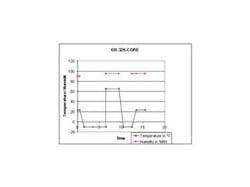
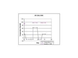
By thermally cycling the device first, the humidity test is more effective because it infiltrates any cracks or gaps that may have occurred. The most challenging of these tests for an environmental chamber is the "humidity/condensation cycle" because test chambers are designed to avoid creating condensation on test samples (see Figure 1). Telcordia recommends heating the chamber up as quickly as possible to create condensation, going from -10 ° C to 65 ° C in 15 to 20 minutes. Not all test chambers can change temperature this quickly. It is even harder to generate humidity significant enough to create condensation in such a short span of time. Some companies have looked at modifying the humidity system to run at full output during this step to effectively create condensation. It is likely that many components manufacturers' tests have been done without ensuring condensation is created, since it is so hard to do so.
Branching components perform more complex tasks than connectors. These devices are not as susceptible to environmental conditions because they are enclosed. But as with electronics, it cannot be assumed that sealing or packaging will protect the device. Moreover, as the signal paths are made smaller, the potential for material-related losses increases.
Like the GR-326-CORE tests for connectors, the GR-1209-CORE tests for branching components can all be done in a single test chamber, simplifying setup. The testing range for two tests is dependent on the application of the device. If the component is to be used in the controlled conditions of a switching station in the central office (CO), more limited testing is allowed. Devices destined for use in uncontrolled (UNC) conditions have more extreme temperature ranges.
The "temperature/humidity cycle" test requires ramping of temperature and humidity at the same time, which is sometimes difficult for low-performance test chambers to do. That's because relative humidity is a function of temperature; so as the temperature changes, it affects the humidity level. The test specification allows for temporary humidity levels of 90%. Each cycle includes a period below freezing (-10 ° C or -40 ° C), where humidity conditions are uncontrolled.
Telcordia established a separate specification for branching components that focuses on long-term reliability, the GR-1221-CORE. That is obvious based on the three-month time periods required for some tests. Like GR-1209, the testing requirements are divided into CO and UNC methods, with longer tests required for devices used in uncontrolled conditions. Because of the long-term nature of these tests, individual test chambers are commonly used for each test. For example, it is better to buy a lab oven and freezer to do the storage tests. The temperature cycling test requires an air-to-air thermal shock chamber.
For the purpose of customers evaluating products, three "quality levels" have been created so that a vendor may concisely state the level of its compliance to the standard. The highest, level III, requires periodic requalification, 100% screening of initial lots, and a continuous reliability improvement program. In fact, much of GR-1221 includes descriptions of quality standards and methodology that must be interpreted for individual product types. It shows the challenge in creating "recipe books" for quality assurance testing that cover a broad product group.
Testing setup
Telcordia standards designate set quantities of samples that must be tested at a time, making test systems predictable and reusable. Since the devices are quite small, the tests can be done in standard environmental chambers.
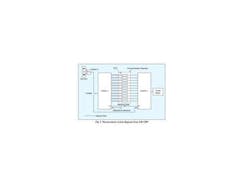
The standards also require active monitoring of the devices during environmental testing; therefore, the interconnection between the test measurement system and the samples is a consideration. Figure 2 is an example of a measurement system to test a batch of branching components. Note that there are two reference signals, as all measurements made are relative, not absolute. One channel shows the insertion loss of the circuit without the device under test (DUT). The other creates a reflectance reference value without the DUT. The switches allow the DUT and references to be tested in succession.
The test standards do not require frequent measurements, but the components are often measured continuously because they need to be set up for measurement anyway. Measurements are performed at the two most common frequency ranges: 1310 and 1550 nm. At the end of each test, any failed components are replaced with other components successfully exposed to the same conditions. GR-326 calls these "hot" samples, which allow the same sample size to be maintained for all tests.
Each standard has minimal requirements for insertion loss and reflectance. The standards also list conditional requirements, which some customers may require. In addition, there are objectives that Telcordia recommends as goals for the performance of the product.
With testing, there are physical issues of fiber management or how to best arrange the samples and the signal fibers for easy setup. Often the delicate fibers used are unshielded, making them difficult to route through standard cable ports on test chambers without a method of carefully sealing the port. One solution to this problem is to use a small tray with dividers (or teeth) to separate the fibers and allow sealing closely to the tray without crushing the fibers. A special flat port is used to do that. Others may devise their own sleeve or shield if using a conventional round cable port.
The reliability of passive fiber-optic components is assured by following the testing methods outlined by Telcordia standards. Although some may view these standards as no more than "recipes" to follow to verify qualification, it is not that simple. Product qualification based on these standards is a process of multiple tests where each step must be clearly defined by the tester. Thus, the tester can create a repeatable testing process to ensure that passive-component specifications are reliable and comparable.
David Jung is an application specialist at ESPEC Corp. (Grand Rapids, MI), a wholly owned subsidiary of Tabai Espec (Japan). The company's Website, www.espec.com, has a section specifically on the Telcordia standards.

