Swept-wavelength testing advancements
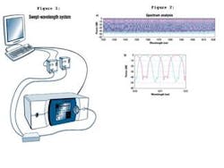
Figure 1. Swept-wavelength (SW) systems are similar to step-and-measure systems. Both consist of a tunable laser, a device under test, receivers, and a data acquisition system. In the SW system, the laser continuously sweeps over the wavelength range of interest.
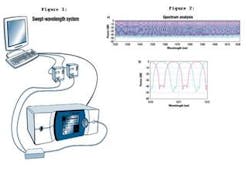
Figure 2. Wavelength measurements made on a 100-GHz interleaver (a), showing both outputs, taken in 1 sec with 3-pm resolution. Traditional step-and-measure systems would take hours to measure even half of this range at one-third the resolution. An expanded view (b) details the high dynamic range of the swept-wavelength system.
By MARK WIPPICH
New Focus
With the growing complexity of DWDM systems-more channels, narrower channel spacing, wider wavelength range, and higher speeds-it's important to fully characterize the wavelength-dependent optical properties of network components. Properties such as insertion loss, wavelength flatness, dispersion, and polarization-dependent loss each can adversely affect network-system performance and therefore must be measured not only at the channel of interest but over the entire wavelength band.
Traditional wavelength characterization methods like those based on optical spectrum analyzers (OSAs) or step-and-measure tunable lasers lack the necessary resolution, are too noisy, or simply take too long. Simple transmission measurements using a high-resolution, low-noise, step-and-measure laser can take up to a few hours to complete; the result is serious manufacturing bottlenecks.
An ultra-fast characterization method would remove this bottleneck and enable continuous testing capabilities. Moreover, because many high-performance devices are trimmed during the manufacturing process itself, an ultra-fast characterization method could improve manufacturing yield and throughput by providing real time feedback and enabling real time in situ capabilities.
Efficient manufacture of passive components for DWDM fiber-optic networks requires an ultra-fast measurement system with high dynamic range and high wavelength accuracy. A method that can deliver the speed, resolution, and dynamic range required is the swept-wavelength (SW) method. It enables continuous testing as well as provides real time feedback.
Swept-wavelength vs. traditional methods
The SW system is similar to the traditional step-and-measure (SM) system in that it consists of a tunable-laser source, a device under test (DUT), optical receivers, and a data acquisition system (see Figure 1). It differs from the traditional SM system in that the specific requirements of the source and receivers are different. In the SM system, the source is "stepped" through the wavelength, dwelling for a period of time at each step for the data to be taken.
In the SW system, the wavelength is swept continuously at a constant rate while the output is recorded, providing a very-high-resolution spectral picture-fast enough to observe changes as a component is being adjusted-and delivering the resolution of a laser with unprecedented speed over an OSA. A good SW source must have a very fast, linear, repeatable and mode-hop-free scan (today's systems offer 100-nm/sec sweep speeds), with adequate absolute wavelength accuracy and resolution and high output power stability. Moreover, the system must have a stable and low-jitter trigger-the signal that alerts the data-acquisition system (whether a computer or an oscilloscope) to begin to take data. The trigger jitter, in conjunction with the laser's relative and/or absolute wavelength accuracy, determines the measured relative and/or absolute wavelength accuracy. Wavelength repeatability from scan to scan is also important when making real time adjustments. Any inaccuracy will cause the data to shift with respect to wavelength from scan to scan, and determining real time changes from spurious shifts will be difficult.
The other difference between the SW and SM system is in the detection. In an SW system, the receiver (or receivers, if monitoring multiple outputs) must have a high dynamic range as well as moderate bandwidth. Calibrated power meters generally cannot be used because they are too slow. For a system with 100-nm/sec sweep speeds, typical bandwidths of a few hundred kilohertz are required.
SW characterization in manufacturing
A few manufacturers already use SW systems on their manufacturing floors. The time savings is dramatic. The use of SW systems allows technicians to final test all devices rather than batch test, which results in a significant increase in yield due to the incorporation of in-process testing.
Consider measuring the throughput of an interleaver product using a traditional SM system consisting of a tunable laser, a DUT, and power meters. For a 100-GHz interleaver with an input spacing of 100 GHz (0.8 nm) and an output spacing of 200 GHz (1.6 nm), a typical measurement from 1525 to 1565 nm in 0.01-nm steps requires 4,000 wavelength points. Using the traditional step-and-measure setup, the data required more than 2 hours to gather. With the swept-wavelength system, this same measurement was performed in less than 1 sec (see Figure 2). Recently, an interleaver manufacturer incorporated the SW system as an in-process test for alignment. Using such a system, manufacturers typically make measurements in less than 1 sec with data update rates of up to 2 Hz. By incorporating this system, their manufacturing throughput and yield are greatly increased.
Advances in SW lasers
New developments in the design of SW lasers have resulted in significant improvements in the noise performance, reliability, and wavelength coverage of SW systems, enabling their use in demanding applications. The most advanced systems now offer 100-nm/sec sweep speeds, 70-dB integrated dynamic range, true 24/7 reliability, and C- and L-band coverage with a single system.
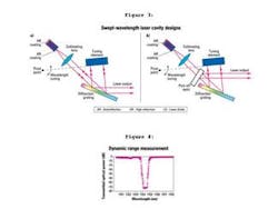
Most SW lasers are built on the Littman-Metcalf cavity configuration shown in Figure 3. This configuration is capable of extended single longitudinal mode tuning without any mode-hops by rotating the cavity retro-reflector about a pivot point. 1, 2, 3, 4 Recent advances in the anti-reflection (AR) and high-reflection (HR) coatings of the Fabry-Perot (FP) laser diode have allowed these lasers to achieve extended wavelength tuning. In these systems, the indium gallium arsenide phosphide (InGaAsP) FP diode can output power in excess of 10 dBm at diode currents that allow operation for more than 50,000 hours. The cavity design, with its specially chosen pivot point, provides wavelength tuning, without mode-hopping, over the entire C- and L- bands (1520-1620 nm).
The standard design shown in Figure 3 couples the laser output power using the zero-order specular reflection off the diffraction grating. This output includes an unfiltered amplified spontaneous emission (ASE) pedestal from the laser diode and therefore has limited spectral purity and a fairly broad noise spectrum. Reducing the ASE is important, because this ASE pedestal contributes to the overall noise spectrum of the measurement and is most often the limiting factor in a measurement's dynamic range. The signal-to-ASE ratio-integrated over all wavelengths-is especially important, because receivers are insensitive to wavelength and so integrate all the incident power regardless of wavelength.
A common technique for reducing the ASE uses an external tunable filter that tracks the laser's wavelength. Such techniques can reduce the ASE by up to 20 dB or more but add considerably to the test-system complexity. Because these filters are typically FP etalon devices with free-spectral ranges of less than the 100-nm tuning range of the C- and L-band lasers, they leak a considerable amount of ASE at the neighboring transmission peaks. Moreover, these filters add a slight ripple to the output power of the laser and destroy its output polarization state. Lastly, many filters simply cannot tune over the entire 100-nm tuning range required for C- and L-band coverage.
A simpler method uses the cavity configuration shown in Figure 3b. Here, a partial reflector is inserted between the grating and diode to output a portion of the emission returning from the grating. 5, 6 This emission has a wavelength-dependent angular distribution, so the fiber coupling results in spectral filtering of the ASE. The cavity uses an intra-cavity pick-off placed perpendicular to the grating surface to allow the filtered output to be parallel to the zero-order output. Selection of the amount of ASE is therefore a matter of simply translating the fiber input, and the ASE can be reduced by well over 45 dB at certain wavelengths.
Keep in mind that ASE is wavelength-dependent, so it is often specified at a given distance by using an OSA at a specified resolution bandwidth-typically 0.1 nm. However, the most telling specification is the integrated dynamic range (IDR), which is the signal-to-ASE ratio-integrated over all wavelengths. That is also what the receiver will see in the measurement system. One method to measure the IDR is to observe the spectrum of high-rejection-ratio filters, where the filters reject the laser-carrier wavelength while transmitting most of the ASE.
The spectrum shown in Figure 4 was taken with two cascaded 60-dB fiber Bragg gratings (FBGs), with a total rejection ratio of >100 dB and a power meter with >100-dB dynamic range. As the laser wavelength was scanned across the FBGs, the measured rejection ratio was limited only by the noise spectrum of the laser. The rejection ratio is a measurement of the ratio of the signal to the total integrated source emission outside the bandwidth of the filter. That is the achievable wavelength-integrated dynamic range and offers a realistic expectation of what is seen in a typical measurement. As shown in Figure 4, the residual transmission of -75 dB at the filter center is a measurement of the ratio of the signal to the total integrated source emission outside the bandwidth of the filter.
Finally, reliability is a key factor for lasers used on the manufacturing floor. Because these swept-wavelength lasers must scan continuously for most if not all hours of the day, it is important that their tuning mechanism exhibit superior lifetime and repeatability. Some designs offer both high speeds (100 nm/sec) and excellent lifetime performance over 10 million cycles. By using an SW meter based on a gas-absorption cell, it's possible to maintain the drive linearity achieving absolute wavelength accuracy (AWA) of 3 pm or better during operation. AWA is defined as the maximum difference between the predicted wavelength (based on assumed linear motion) and true wavelength throughout the entire tuning range. The SW meter uses a gas absorption cell for absolute wavelength reference and an interferometer for wavelength interpolation and extrapolation over tuning ranges beyond the gas absorption lines.
The efficiency of wavelength characterization measurements has become more of an issue as DWDM systems mature to more channels with narrower spacing at higher speeds. The swept-wavelength method offers the speed, resolution, noise performance, and reliability required for demanding applications on the manufacturing floor.
Recent advances in laser design have made systems available that have 100-nm/sec sweep speeds, better than 70-dB dynamic range, sub-picometer resolution, and excellent accuracy, repeatability and reliability. Because of their speed and overall superior performance, these systems help drive down the costs of manufacturing passive components by enabling continuous test and adjustment capabilities. These lasers will provide invaluable cost savings to manufacturing environments in which yield and throughput is key to keeping costs down.
Mark Wippich is a product marketing manager at New Focus Inc. (San Jose, CA).
References
1. M. Littman, "Single-mode operation of grazing-incidence pulsed dye laser," Optics Letters, Vol. 3, No. 4, October 1978, pp. 138-140.
2. K. Liu and M. Littman, "Novel geometry for single-mode scanning of tunable lasers," Optics Letters, Vol. 6, No. 3, March 1981, pp. 117-118.
3. K.C. Harvey and C.J. Myatt, "External-cavity diode laser using grazing-incidence diffraction grating," Optics Letters, Vol. 16, No. 12, June 15, 1991, pp. 910-912.
4. U.S. Patent No. 5,319,668, "Tuning System for External Cavity Diode Laser," June 7, 1994.
5. C.E. Weiman et al, "Using diode laser for atomic physics," Review of Scientific Instruments, 62 (1) January 1991.
6. E. Leckel, J. Sang et al, OFC 2000 (WB4 Baltimore).
Figure 3. Swept-wavelength lasers are built on the traditional Littman-Metcalf configuration (a). A modified version of this configuration (b) lowers amplified spontaneous emission to better than 70 dB.


