Managing chromatic dispersion in the network
By FRANCIS AUDET and PETER CLARK
EXFO Electro-Optical Engineering Inc.
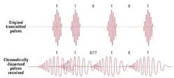
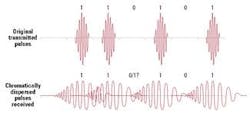
Chromatic dispersion is the phenomenon whereby the velocity of light propagation in a material varies with wavelength. All light comprising a communications system contains a spectrum of wavelengths. No matter how sharp the laser, it always has a finite width, which is increased by chirp and modulation. Because all these wavelengths travel at different velocities through the fiber, dispersion will occur over a length of fiber, causing pulse spreading, and limiting the overall data rate in the fiber as shown in Figure 1.
New developments in high capacity transmission systems have meant that more attention must be paid to this parameter. With the advent of DWDM and higher power, higher bit rate systems, chromatic dispersion measurements in the field are now essential for reliable network commissioning and operation.
Fiber characteristics
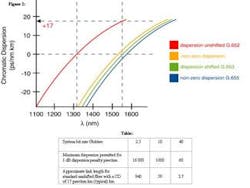
Unlike polarization-mode dispersion, chromatic dispersion increases linearly with fiber length and is constant with time. Most fiber-optic networks are composed of standard singlemode unshifted fiber (see Figure 2). The wavelength at which dispersion is minimal is called lambda zero. For unshifted fiber, this wavelength is around 1310 nm, but modern systems operate in the 1550-nm range where the dispersion for unshifted fiber is high. If unshifted fiber is used with 10-Gbit/sec systems, or systems with even higher bit rates, chromatic dispersion characterization and compensation is required. Table 1 shows the maximum levels of chromatic dispersion allowed for various bit rates.
The non-linear properties of a fiber must also be taken into consideration. Single-channel systems use power levels in the 20-mW range. With the introduction of amplifiers and multi-channel DWDM systems, power levels many times this can be found. High optical power can cause light pulses to interact with other pulses. Careful dispersion management is required to minimize this effect.
Non-linear effects
Two significant non-linear effects can occur: modulation (self-phase and cross-phase), and four-wave mixing. Both effects are dependent on chromatic dispersion.
Four-wave mixing occurs most often. When two or more optical frequencies are present in a non-linear system, sum and difference products will be generated. The longer the two signals remain in phase with each other, the greater the interaction. Chromatic dispersion will reduce the distance the signals are in phase and reduce four wave-mixing effects. This reduction is critical for DWDM systems, where a number of channels are present and generated pulses are certain to fall within other DWDM channels, reducing the overall system signal-to-noise ratios. This can be balanced by dispersion-management schemes that ensure overall average chromatic dispersion is very low and varies positively and negatively along the route, while never reaching zero at the operating wavelengths.
Table 1 shows the maximum chromatic dispersion that can be tolerated by a system for a power penalty of 1 dB. Increasing the bit rate by a factor of four reduces the permitted dispersion by a factor of sixteen (four times the bit rate means the pulses are four times closer and the modulation sidebands are four times wider).
Optical networks generally consist of old and new fibers, both of which must be used optimally. While the average dispersion in the 1550-nm window can be estimated from old 1310-nm data, this figure is not accurate enough for high-bit-rate systems. For unshifted fiber, the dispersion at 1550 nm can vary from 16 to 20 psec/nm?km. This 4-psec variation is too much to tolerate and measurements must be made. In some systems, shifted and unshifted fiber may be mixed, producing unusual dispersion characteristics. For multi-channel DWDM systems, accurate dispersion mapping is required at all wavelengths and chromatic dispersion measurements are essential.
Methods of measurement
Chromatic dispersion is determined by measuring the variation in arrival times of pulses of various wavelengths sent down the fiber, or by using a modulated variable wavelength source and measuring the change of modulation phase with wavelength.
A simple way of implementing the first method is to use different lasers all activated from a single pulse generator. The first laser wavelength is used as the reference time delay to which the other wavelengths' transit times are compared. A curve is fit to these points and then differentiated to produce the final chromatic dispersion curve. Despite this method's simplicity, errors can be introduced when locating the position of the pulses in time, particularly as they are widened by chromatic dispersion. In addition, due to cost, generally only a few wavelength-stabilized lasers are used, and this limited number of points decreases precision.
A favored method for measurement, as described in the Telecommunications Industry Association's Fiber Optic Test Procedure 169, is the phase-shift method. Due to cost, a modulated light-emitting diode-combined with a monochromator-is used to select wavelengths within the range of interest. The idea is to measure the change in phase of the detected signal as the wavelength is altered. Data is then fit to a curve, which is then differentiated to produce chromatic dispersion data. This method is flexible and allows the number of measurement points and wavelength ranges to be varied.
For all methods, it is critical to choose the correct curve to fit the data. The variation of chromatic dispersion with wavelength is not a simple linear function. The best solution is always to measure the range of system-operating wavelengths-normally the C- and/or L-bands-to determine the exact amount of compensation required.
Chromatic dispersion compensation and management
Once the installed fiber is characterized, the next task is to install compensation systems to bring the total chromatic dispersion within the transmission system's operating limits. There are a few factors to take into account. First, is compensation required over a band of wavelengths or just at one wavelength? Second, remembering non-linear effects, can the compensation be made at one point or should it be distributed along the cable route to manage the minimum and maximum dispersion extremes at any point?
These factors determine which of the two major compensation techniques should be used. The most common technique uses dispersion-compensating fiber (DCF). This fiber has a much higher dispersion level in the opposite direction to that of standard fiber (typically 10 times). The loss of this extra fiber needs to be taken into account. The second type of compensator available is the chirped fiber Bragg grating. These gratings are very small and operate over narrow wavelength ranges compared to the kilometers of DCF required. Generally, one grating is needed per DWDM channel. However, because gratings are specialized and more precise, this is a more expensive solution.
Wideband chromatic dispersion compensators
Although the issue of chromatic dispersion is a little more complex than first thought, if the external fiber network is accurately characterized, then there are ways of applying compensation to maximize the bandwidth capabilities of the system. The widespread use of DWDM systems covering the C- and L-bands (1530 to 1625 nm) will generate the need for accurate wideband chromatic dispersion compensators. Chromatic dispersion, a phenomenon originally only measured in the factory, now needs to be characterized in the field.
Francis Audet is an engineering product manager at EXFO Electro-Optical Engineering Inc. (Quebec City, Canada). Peter Clark is an engineer and was formerly a scientific director for EXFO in the United Kingdom.

