Polarization-dependent loss measurements with the Mueller method
Polarization-dependent loss measurements with the Mueller method
The Mueller method is just as accurate as the more established scanning technique and promises shorter testing times and more-complete polarization characteristics.
CHRISTIAN HENTSCHEL, Hewlett-Packard, Boblingen Instruments Div.
Measurements of polarization-dependent loss (pdl) are becoming increasingly important because of today`s optically amplified systems. These networks are transparent from end to end, making them sensitive to the accumulation of imperfections. One of these imperfections is the pdl of the optical components used.
Traditionally, a pdl measurement is accomplished by applying all polarization states to the device under test (dut) and recording the minimum/maximum values. This is a robust and accurate technique that is frequently called polarization scanning.1 Its main disadvantage is that searching for the minimum/maximum states takes time. Particularly in wavelength-dependent pdl measurements, a large number of measurements have to be carried out.
Recently, a technique called the Mueller method has been developed and internationally standardized.2,3 In this method, only four polarization states are generated. The Mueller method is faster than polarization scanning and provides additional information about the test device.
Mueller method
The Mueller method is based on applying four well-known polarization states to the test device. The optical power is measured at these four states, and the pdl is calculated from the four power results. The theory of the Mueller method is explained in Reference 4. Only a short abstract is presented here.
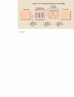
The measurement setup for pdl measurements with the Mueller method is shown in Fig. 1. The key instrument is a waveplate-type polarization controller, which synthesizes the polarization states with the help of two bulk-optical waveplates, a quarter-waveplate (Q), and a half-waveplate (H). A polarizer (P) is added in front of the waveplates to ensure a polarized signal with known state to start with. Therefore, the first step in using this setup is to rotate the polarizer until a best match with the incoming signal occurs and maximum transmission is achieved. The Q and H plates are always to be oriented with reference to the rotation angle of the¥plate.
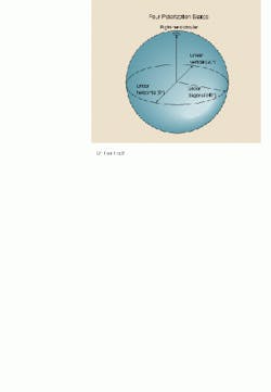
The Poincaré sphere is increasingly used as a graphical representation of different polarization states. Figure 2 shows a Poincaré sphere with the four polarization states applied to the test device. Obviously, the four states form a rectangular system.
The procedure starts with a calibration in which the optical powers at the four polarization states are measured. The intention is to remove any power changes due to the rotation of the waveplates from the measurement result. Then the dut is inserted and the power is measured again at the same polarization states. From the power results, the maximum and minimum transmissions through the dut can be calculated:
where the pdl is simply the logarithmic ratio of Tmax and Tmin
The elements m11 through m14 represent the first row of the Mueller matrix (not further explained here). These elements can be calculated from the eight power results (the calibration results are subscript with minor letters; the dut measurement results are subscript with capital letters):
A few points have to be observed to ensure accurate measurement results:
Repeatable input power--Power
changes due to rotating the waveplates are expected to be repeatable. Quite often, it is overlooked that laser sources react with unstable power when light of varying polarization states is backreflected, as in this measurement. Therefore, an attenuator or isolator should be inserted between the source and the polarization controller.
Accurate control of polarization
states--As shown in Fig. 2, the four polarization states at the input of the dut must form a rectangular system. This is the responsibility of the polarization controller. A rotation of the whole system on the Poincaré sphere--for example, during the transit through fiber 2--has no influence on the pdl result.
Polarization-independent power
meter--For this application, a power meter with the lowest possible polarization dependence should be selected, because the power meter`s pdl adds directly to the measurement uncertainty. In addition, it is advisable to use an optical power meter with high return loss, because otherwise additional uncertainty due to optical interference may occur. This is particularly important when the source is a narrow-linewidth tunable laser.
Compared to with the scanning method, the Mueller method offers both advantages and disadvantages. The uncertainty of the Mueller method is approximately the same as that of the scanning method: ۪.01 to ۪.02 dB are achievable when using appropriate equipment. The Mueller method must be controlled by a computer, whereas the scanning method need not. The Mueller method needs a calibration step. Another complication is that the waveplates produce the desired delays only within a relatively narrow wavelength range, i.gif., between 1520 and 1570 nm. For other wavelengths, the waveplate settings must be selected from a lookup table (see Reference 4).
An advantage of the Mueller method is its speed: less than 2 sec per pdl value can easily be achieved, in comparison with 5 to 10 sec for the polarization-scanning method. Another advantage is the possibility to generate well-defined polarization states, as discussed below.
Wavelength-
dependent pdl
measurements
Systems with wavelength-division multiplexing (wdm) add another level of complexity to the performance verification of optical components: wavelength-dependent pdl measurements. In these measurements, a fast pdl measurement technique is essential. Figure 3 shows a wdm demultiplexer, a typical component that must be tested for wavelength-dependent pdl. Two types of measurement results may be desired:
wavelength-dependent pdl, for exam-
ple, in addition to the average insertion loss,
polarization-dependent wavelength
shift, which describes how the filter curve changes when different (fixed) states of polarization are applied to the dut. Notice that this information cannot be obtained from the measurement data gathered for wavelength-dependent pdl.
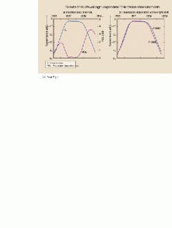
Figure 4 shows actual measurement results of one channel of an eight-channel wdm demultiplexer. Key characteristics of this demultiplexer are channel separation of 1.6 nm, 3-dB channel width of 1.4 nm, and passband insertion loss of 3 dB. The pdl was wavelength-dependent between 0.06 and 4 dB, and the maximum polarization-dependent wavelength shift was 0.08 nm.
Polarization-dependent wavelength shift
The measurement of polarization-dependent wavelength shift requires generating the polarization states that lead to minimum and maximum transmission. These polarization states are termed J- and K-states (see Fig. 4), which can also be calculated by the Mueller mathematics (not shown here; see Reference 4). The suggested measurement setup is the same as that in Fig. 1, except that a tunable laser replaces the single-wavelength laser.
The measurement is started by selecting a wavelength at which the pdl is relatively high--for example, on the slope of the filter curve as in Fig. 4. Then the J- and K-states for that wavelength are calculated and generated with the polarization controller (notice that these states may be anywhere on the Poincaré sphere). Finally, the wavelength-dependent power is measured by scanning over the required wavelength range and repeating the J- and K-states for each wavelength.
One goal for this measurement should be wavelength-independent polarization state. An experiment using the HP 8168F tunable laser source, the HP 8169A polarization controller, and the HP 8509B polarization analyzer showed that the change of polarization state can indeed be neglected, at least for the wavelength range of 1520 to 1570 nm selected in this test.
The uncertainty is approximately the same as that of regular pdl measurements. The only additional requirement is that the polarization transformation of fiber 2 must be constant during the measurement because any movements mean that the J- and K-states are lost. Taping the fiber to the bench is recommended to achieve constant polarization transformation. The applicable wavelength range is 1520 to 1570 nm. At other wavelengths, it is more difficult to synthesize the J- and K-states because of the wavelength- dependent optical delays of the waveplates.
Summary
This paper has discussed pdl measurements with the Mueller method, particularly in light of wavelength-dependent pdl measurements. The most important conclusions are that the Mueller method is as accurate but faster than the scanning technique, and that it delivers more complete polarization characteristics, here called polarization-dependent wavelength shift. u
References
1. "Polarization dependent loss measurements using modular test system configurations," Hewlett-Packard product note 11896-1, 1996.
2. B. Nyman, "Automated system for measuring polarization-dependent loss," Optical Fiber Communication Conference, OFC 1994, Technical Digest, ThK6, p. 230.
3. iec 61300-3-12: "Polarization dependence of attenuation of a single-mode fiber optic component: Matrix calculation method."
4. S. Schmidt, C. Hentschel, "pdl measurements using the HP 8169A polarization controller," Hewlett-Packard publication no. 5964-9937E.
Christian Hentschel is standards laboratory manager at the Hewlett-Packard Boblingen Instruments Div., Boblingen, Germany.Fig. 4. Results from wavelength-dependent polarization measurements include insertion loss, pdl, and polarization-dependent wavelength shift.


