Putting the lens to optical-layer protection
Putting the lens to optical-layer protection
Much has been said about optical-layer protection. But the best way to provide this protection could vary with your application.
Rob Batchellor, Ericsson Inc.
The deployment of dense wavelength-division multiplexing (dwdm) systems in the transport layer is easily justified on the bases of cost savings and speed of installation. The economic benefits in terms of enhanced capacity, ease of installation, and reduced equipment inventory are clear. Yet aside from simple multiplication of transmission capacity, the attributes of dwdm systems remain a subject of active debate within the telecommunications industry. Nowhere is this more apparent than in the area of optical-layer protection.
For the first time, dwdm systems offer the possibility to implement a universal transmission layer for all client traffic types. A single optical network can provide simultaneously the interconnection fabric for Synchronous Optical Network (sonet), Asynchronous Transfer Mode (atm), Internet protocol (IP), and other client layers. This flexibility provides operators insurance against the uncertainties of tomorrow`s traffic mix and enables the elimination of redundant equipment strata from the service layer stack.
What is optical protection?
Optical protection is commonly understood to be a mechanism implemented within the optical layer, which provides for prompt restoration of a failed dwdm link. It operates at the aggregate level, i.e., with the entire channel multiplex, permitting the cost and management overhead of the feature to be amortized over the number of channels present.
Optical-protection schemes divide into those supporting linear structures (point-to-point wdm) and those supporting wdm rings. In rings, optical protection may be implemented in two ways, which are directly analogous to the unidirectional path-switched ring (upsr) and bidirectional line-switched ring (blsr) mechanisms of sonet.
In a point-to-point system, optical protection operates by detecting a fault on the line (by simple loss of aggregate signal or by degradation of the bit-error rate) and responding by switching the traffic multiplex to a backup disparate route. Switching can be achieved using optical switches. One major drawback to this scheme is that there is no way to be certain that the optical switches will operate when an outage occurs. An alternative to optical switches is to activate and deactivate the optical preamplifiers that serve the working and protective path. This approach has the advantage of permitting comprehensive monitoring of the status of the protection path.
Optical protection has limited application when the point-to-point systems incorporate linear optical add/drop multiplexers (oadms). While end-to-end traffic will be protected, traffic extracted or inserted at the intermediate oadms is not.
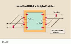
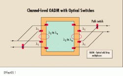
In upsr-like optical rings, channels are routed either one way or the other around the ring, depending on the presence of faults. This routing can be achieved by optical switches operating at the channel level and placed at the channel end-nodes (see Fig. 1). The number of wavelengths supported by the ring determines the maximum number of logical connections the ring supports (each channel occupying one wavelength in the total circumference of the ring).
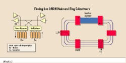
An alternative approach, again upsr-like, is the flexing bus, which achieves the same protection through a simpler and more elegant architecture. The flexing-bus oadm structure and a flexing-bus ring subnetwork are shown in Figure 2. Traffic entering the subnetwork at an oadm is transmitted in both directions, but because one segment of the ring is inactive, a channel will only be received at its destination node from one direction or the other. Figure 2 shows one such bidirectional channel in a subnetwork of six oadm nodes. Note that the counter-propagating traffic signals may be assigned the same wavelength channel, since superimposition of signals does not occur between source and destination nodes. In addition, the architecture implicitly supports unidirectional broadcast, since any channel injected into the ring is available at all nodes.
In the event of a fiber or optical amplifier failure within the ring, the bus reconfigures so that the inactive segment in the ring encompasses the segment affected by the failure. The previously inactive segment is simultaneously activated. This process restores all traffic paths irrespective of their source and destination oadms.
The restoration mechanism can be implemented so each oadm acts autonomously and without local knowledge of the channel or subnetwork topology. In addition, there are no channel filters present within the ring fibers, because the ring always contains an inactive segment, and thus no special mechanism is required to prevent channel recirculation. Onerous alignment tolerances of lasers and concatenated optical filters are avoided, and it is very simple to add a new channel or node to an operational ring. The existence of an inactive segment that can be moved about the ring at will also eases such operational issues as planned maintenance and changes to the ring topology. Furthermore, optical switches are avoided, since segments are activated and deactivated by toggling the state of the adjacent optical amplifiers.
blsr-like rings allow each wavelength to be reused many times but at the loss of ease of reconfiguration. Since inline channel-blocking filters are required, adding or changing the routing of a logical channel requires changing the filters, which introduces disturbance to other traffic.
Protection is provided by a second pair of fibers on the ring that are used to carry the traffic affected by a segment failure. This traffic is routed in the opposite direction around the ring. A possible implementation of a blsr node is shown in Figure 3, which shows two wavelengths being added/dropped, using hypothetical dwdm extract/insert couplers.
Why optical protection?
Protection in the optical dwdm layer is not a universal panacea. Its merit depends both on the logical topologies of the client layers and their inherent resilience.
A clear example of where optical protection is not advantageous is when dwdm is applied to overlaid sonet blsr or upsr rings to reduce fiber consumption. Here, the client layer already protects all the traffic carried by the optical layer (assuming that the physical topology of the optical layer preserves the diverse routing offered by the sonet ring). Any optical protection measure represents unnecessary duplication and a squandering of network capacity.
Where the optical layer provides point-to-point links, such as atm interconnections or traffic in a sonet backbone mesh, optical protection may provide benefits. The degree of benefit is dependent on the approach taken to channel protection, which in turn depends on the inherent resilience of the client layer.
The clients of the optical layer fall into two broad categories of approaches to traffic resilience: those that protect through switchover (e.g., sonet) and those that have the potential for prompt traffic rerouting (e.g., atm and IP). Each category places different protection demands on the superincumbent optical layer.
sonet and asynchronous networks are examples of switched-protection networks in which a channel fault is handled by switch over to an alternative channel path. Traffic also can be restored by rerouting at digital crossconnects around the failed channel using spare capacity on other routes. But this process is unacceptably slow in today`s commercial climate. Channel protection therefore is usually provided.
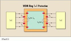
The protecting channel may be dedicated (1+1) or shared between a set of parallel channels (1:N). For 1+1 protection in healthy network conditions, the traffic is transmitted through both channels, and the optical network must support both channels for it to be transparent to sonet. If these channels are diversely routed within the optical layer, then no additional protective measure is needed within the optical layer. In a wdm ring, for example, each channel travels in disjointed ring segments (see Fig. 4). If suitable optical filtering is used, then the same wavelength may be used for both channels
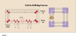
If the working and protecting channels have the same routing through the ring (as would be advantageous when wavelength reuse is available), then optical line protection will be required (see Fig. 5). A point-to-point channel exists between adjacent nodes of a blsr-like wdm ring. Two wavelengths are used to provide channel protection, and these are routed parallel to each other so as to allow their reuse on either side of the point-to-point link. The blsr action of the wdm ring then provides the necessary protection against line failures between the nodes.
Optical protection also is necessary in all 1:N channel-protection schemes. When combined with wdm, 1:N can only protect against channel failures, not line failures. upsr and blsr-like optical rings are suitable for supporting 1:N links, one offering architectural and operational simplicity and the other, better utilization of wavelengths.
Given the condition that parallel sonet channels are present within the network, 1:N channel protection combined with optical line protection appears to be a very efficient means of providing comprehensive traffic protection. The 1:N scheme avoids complete duplication of equipment to protect against sonet interface or tributary interconnect failure, while optical protection provides cost-effective protection against route fiber and equipment failures.
dwdm offers universality
Fast restoration in the optical layer enables transport of client layer atm, IP, or other traffic without requiring a sonet layer for protection. dwdm systems offer the possibility of implementing a universal transmission layer for all client traffic types. Optical protection is available for linear point-to-point traffic and in upsr-like ring applications. wdm systems with blsr-like ring functionality will be available in the near future.
When the optical layer carries point-to-point sonet traffic and that traffic is 1:N channel-protected, then optical protection is a highly efficient means by which to provide line protection. That`s also true for point-to-point 1+1 channel protection links where the working and protecting channels are not diversely routed for reasons of efficient wavelength utilization.
The flexibility of wdm systems with optical protection provides operators with insurance against the uncertainties of tomorrow`s traffic mix and enables the possible elimination of redundant equipment strata from the service-layer stack. u
Rob Batchellor is a wdm solutions expert at Ericsson Inc. (Richardson, TX).Fig. 5. Optical line protection is necessary if the working and protecting channels have the same routing through the ring. The key to such protection is a point-to-point channel between adjacent nodes of a blsr-like wdm ring.
