AOTFs route traffic in WDM networks
AOTFs route traffic in WDM networks
Operating as a key element of an acousto-optic switch, a tunable filter helps perform wavelength switching, dynamic gain equalization and add/drop functions in multiwavelength fiber-optic networks
KARL M. kissa and daniel j. fritz
Uniphase telecommunications Products
To increase aggregate capacity and reduce the cost of routing large volumes of telecommunications traffic, acousto-optic tunable filters (AOTFs) can be used to perform optical signal routing, switching and dynamic gain equalization functions in wavelength-division-multiplexed (WDM) fiber-optic networks.
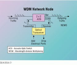
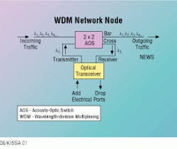
The AOTF, the key element of an acousto-optic switch, is employed to add and drop telecommunications traffic at a WDM network node (see Fig. 1). During operation with an optical transceiver, the switch extracts a designated wavelength--say l2-- from several incoming wavelengths and routes it to the cross port. This wavelength is then converted into the electrical domain by the optical transceiver. New traffic from the network node is transmitted by the transceiver on the same wavelength (l2´).
The acousto-optic switch combines l2´ with the other outgoing wavelengths and sends them all to the next network node. The other incoming wavelengths pass through the switch without being converted to electrical signals; therefore, node switching hardware costs are reduced.
If several transceivers are present at the add/drop node, the acousto-optic switch can add and drop multiple wavelengths. Its operation is independent of standard signal formats, such as Synchronous Optical Network (Sonet), Asynchronous Transfer Mode (ATM) and analog subcarrier-multiplexed (SCM). Additional optical hardware, however, would be required to separate and combine the wavelengths so they could be routed to individual transceivers. The selection of wavelengths can be changed within 10 microseconds, thereby making the network reconfigurable virtually instantly.
Light polarization
Operation of the AOTF as a switch or a filter is based on its ability to convert the polarization of light in an optical waveguide from the transverse electric mode to the transverse magnetic mode, or vice versa, over a narrow wavelength range. A radio-frequency (RF) tone applied to an interdigital transducer generates a surface-acoustic wave. This wave travels along the optical waveguide and causes a conversion to occur at the phase-matching wavelength. The wavelength range of bandpass is typically defined by the full-width half-maximum points of the filter response curve. This range, which depends on the length of the acousto-optic interaction, is typically 1.8 nanometers for common AOTFs.
The birefringence of lithium niobate, a key modulator component of the filter, has a temperature dependence that causes the phase-matching wavelength to have a temperature sensitivity of approximately -0.7 nm/°C. Temperature stabilization of the AOTF is therefore needed to substantially reduce any temperature-induced drift of the filter or switch wavelengths. A sensitivity to ambient temperature as low as 0.01 nm/°C has been achieved for an AOTF thermally cycled in an oven. This sensitivity indicates that wavelength control to ۪.05 nm or better is possible in a controlled laboratory or office environment.
Switch structure
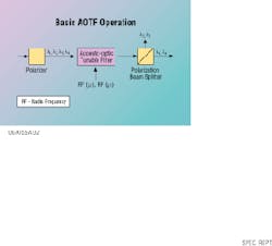
Acousto-optical switching is accomplished by incorporating a polarization beam splitter after the AOTF to separate the converted and unconverted wavelengths (see Fig. 2). For example, if the incoming light is polarized in the transverse electric mode of the waveguide, the AOTF converts the transverse electric mode to the transverse magnetic mode at the wavelength selected by the RF tone. The unselected wavelengths remain in the transverse electric state and are separated spatially from the selected wavelengths by the polarization beam splitter. The net effect is that the selected wavelengths exit the filter`s cross port while unselected ones remain in the bar port. Applying multiple RF tones causes multiple wavelengths to undergo polarization conversion, thereby allowing independent selection of wavelengths to be switched to the cross port.
Arbitrary polarization
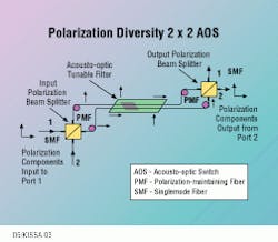
Many applications require the AOTF to switch light of arbitrary polarization, such as that carried by a singlemode fiber. A polarization diversity acousto-optic switch consists of two independent AOTFs on the same chip, combined with an input and output polarization beam splitter (see Fig. 3). Polarization-maintaining fiber carries light to and from the AOTF.
During operation of the polarization diversity 2 ¥ 2 acousto-optic switch, the orthogonal polarization components of light entering port 1 of the input polarization beam splitter are separated and routed to two matched, but independent, AOTFs on the same chip. Light enters the AOTFs as either transverse electric or transverse magnetic polarized light, and is converted to transverse magnetic or transverse electric, respectively, at the selected wavelength(s). The outputs of the AOTFs are routed to the output polarization beam splitter, which recombines the polarization components. Light undergoing polarization conversion (transverse magnetic-to-transverse electric or transverse electric-to-transverse magnetic) exits port 2 of the output polarization beam splitter. All remaining light exits via port 1 of the output polarization beam splitter.
In this application, the acousto-optic switch operates as a conventional reciprocal 2 ¥ 2 switch. Wavelengths selected with RF tones are routed from input port 1 to output port 2 or from input port 2 to output port 1. For the other wavelengths, for which the acousto-optic switch is in the bar state, light entering input port 1 leaves output port 1 and light entering input port 2 leaves output port 2.
Gain equalization
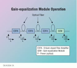
Another application of the AOTF in multiwavelength optical networks deals with dynamic gain equalization of an erbium-doped fiber amplifier. The gain of this amplifier varies slightly with wavelength, and this variation causes a large power imbalance between channels after the optical signal has passed through several amplifiers (see Fig. 4). In addition, the level of imbalance changes as the spectral composition of the optical signal changes. For example, if one or more wavelengths are extracted from the fiber by an acousto-optic switch, the power imbalance between the remaining channels changes. Dynamic equalization by a gain-equalization module restores the proper power balance between optical channels.
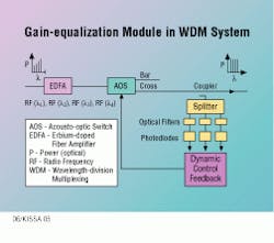
The gain-equalization module consists of an acousto-optic switch operated midway between the bar- and cross-switch states (see Fig. 5). The acousto-optic switch introduces a programmable amount of loss in each optical channel. Monitoring the optical power in each channel and using a feedback loop to control the RF drive power in each tone supplied to the AOTF minimizes the optical power imbalance between channels.
Counter-propagation method
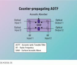
Special configurations can be used to optimize AOTF performance when the spacing of adjacent wavelengths is on the order of a few nanometers. The counter-propagation approach, which consists of two AOTFs in tandem on the same optical waveguide, reduces the interaction between adjacent channels because the surface-acoustic waves for those channels are isolated and therefore do not overlap (see Fig. 6). The RF tones for the even-numbered channels are applied to the interdigital transducers on the left side of the surface-acoustic wave, whereas RF tones for the odd-numbered channels are applied to the transducers on the right side of the wave. In this configuration, a 4-nm channel spacing is demonstrated.
The feasibility of using smaller channel spacings (for example, 3.2 nm) is being investigated. Preliminary studies indicate that smaller channel spacings are possible. In fact, channel spacing has been reduced to 2 nm through the use of wavelength dilation. During this process, even- and odd-numbered channels are separated and recombined with a wavelength demultiplexer/multiplexer. The two sets of channels are then switched independently. A 3.2-nm spacing without wavelength dilation translates into a 1.6-nm spacing with dilation.
Other AOTF enhancements include passband flattening, which makes the cross- and bar-state transmission versus wavelength plot more rectangular, thereby reducing the sensitivity of the acousto-optic switch to laser-switch wavelength registration errors. Spatial dilation has been used with wavelength dilation to reduce the crosstalk level of an acousto-optic switch to nearly -30 dB. q
Karl M. Kissa is senior optical engineer and Daniel J. Frit¥is electro-optics engineer at Uniphase Telecommunications Products, Bloomfield, CT.Fig. 6. A counter-propagating acousto-optic tunable filter (AOTF) configuration is needed for the switching and equalization of closely spaced wavelength-division multiplexed channels. An acoustic absorber placed in the center of the surface-acoustic wave isolates tandem AOTFs. The RF tones for the even- and odd-numbered channels are applied to RF input 1 and RF input 2, respectively. Channel-to- channel interactions are reduced by doubling the channel spacing in each filter.
