Which optical modulation scheme best fits my application?
by Stephanie Michel
We saw in our previous article, "Complex Coding Concepts for Increased Optical Bit Transfer Efficiency," for the example of quadrature phase-shift keying (QPSK), how complex modulated optical signals can be used to express a series of bits by one symbol. Now, we'll learn how this approach reduces the required optical bandwidth. In addition, several modulation schemes will be introduced and compared to provide guidance on the best scheme for your speed class and reach.
New speed for the signal
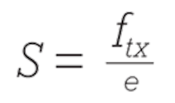
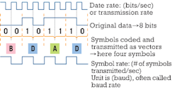
We now effectively deal with two different speeds. First is the bit rate ftx, measured in bits per second, also referred to as "transmission rate." Second, we define the symbol rate S that quantifies the number of symbols transmitted per second, measured in baud and therefore often called "baud rate." With the coding efficiency in bits/symbol: e = log2 (number of symbols in alphabet), the symbol rate calculates as:

Figure 1 illustrates this formula for QPSK. The minimum optical bandwidth required by the signal (in Hz) is determined by dividing the symbol rate by 2. If the signal is also polarization multiplexed, divide this result by 2 as well. For a 100-Gbps QPSK signal, this means, for example, that the symbol rate S = (100 Gbps)/ (2 bits/symbol) = 50 Gbaud. The occupied optical bandwidth is then 25 GHz.
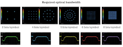
Therefore, the bandwidth required by complex modulated signals doesn't depend on the data rate but only on the symbol rate (see Figure 2). That also means the more bits encoded into one symbol at a given data rate, the greater the reduction in occupied optical bandwidth.
It would be taking too narrow a view though to conclude that in every case a modulation scheme with a higher number of bits encoded into one symbol is the right choice. Apart from the occupied bandwidth, the reach, technical feasibility, existing infrastructure, etc., have to be considered.
Phase-shift keying schemes
In phase-shift keying schemes, the amplitude is constant and information lies in the phase only. Traditional techniques like WDM and polarization-division multiplexing (PDM) can always be used together with any phase-shift keying coding schemes to gain additional data transfer capacity. Multiplexing defines several channels where different phase-modulated signals can be transmitted.
Binary phase-shift keying (BPSK). BPSK is the simplest pure phase-shift keying format. There are two possible phase values separated by 180o, for example: 0 and p (see Figure 3). The amplitude is constant. The large distance between the two symbols makes it fairly immune against distortions and noise compared to on/off keying (OOK). That makes BPSK suitable for ultra-long-haul applications like submarine fiber networks at speeds up to 40 Gbps.

The downside of BPSK, however, is that each symbol represents only 1 bit, just like OOK, which makes it equally inapplicable to 100 Gbps and higher data-rate applications. A disadvantage of BPSK versus OOK is there's no simple solution for determining the absolute phase of a signal. More complex and therefore expensive methods are needed; so-called coherent detection is the key term here. In the case of OOK, the amplitude carrying the information can be detected with just a photodiode. That's also referred to as "direct detection."
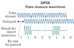
Differential phase-shift keying (DPSK). To avoid the necessity of coherent detection, BPSK can be modified. In a DPSK signal, not the absolute phase p but a phase change by p reflects a zero. If the phase does not change from one bit to the next, this is interpreted as a 1. On the receiver side, the data stream is split into two identical streams that are then delayed by one bit period. Mixing the two data streams (see Figure 4) results in a signal that can be directly detected by a photodetector. The mixing also offers the advantage of a gain in intensity.
But just like in OOK, there is only 1 bit transferred per symbol, which makes DPSK inapplicable for the highest data-rate applications. It is a good choice though for speeds up to 40 Gbps for long-haul and ultra-long-haul.
Quadrature phase-shift keying (QPSK). As we saw in the previous article, one symbol represents 2 bits in QPSK. The four constellation points differ in phase by p 2 and the amplitude is constant (see Figure 5). In comparison to OOK and BPSK, QPSK enables the data rate to be doubled while keeping the same bandwidth, meaning it's also possible to stay at the same data rate at half the bandwidth, with the same bit error ratio (BER). So QPSK is suitable for data rates of 100 Gbps as well. Coherent techniques are needed for detecting the phase of the signal.
Differential quadrature phase-shift keying (DQPSK). To avoid phase ambiguity in QPSK at the receiver side due to phase shifts induced by the fiber, just like in BPSK, a differential variation of QPSK can be used: DQPSK. The information again is in the phase shifts between the transmitted symbols. The four possible phase-shift values are commonly: 0, - p 2 , p 2 , or p.

DQPSK shows lower BER than QPSK, but it's less tolerant to dispersion. As in OOK and DPSK, a DQPSK signal can be detected directly.
Other variants of QPSK won't be explained in detail here, p4 -QPSK, offset QPSK (OQPSK), and shaped-offset QPSK (SOQPSK), to name a few.
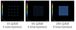
The next step toward higher spectral efficiency is "8-PSK," where one symbol reflects 3 bits. Nevertheless, this format and higher order PSK formats are uncommon in fiber optics. At this level, it's worth considering schemes that combine phase-shift keying (PSK) and amplitude-shift keying (ASK) methods, including quadrature amplitude modulation (QAM). 16-QAM, for example, offers higher spectral efficiency at a BER comparable to that of 8-PSK.
Amplitude- and phase-shift keying schemes
In amplitude- and phase-shift keying schemes, information lies not only in phase, but also in amplitude. Traditional techniques like multiplexing can always be applied to further increase the amount of data transferred per unit time.
Quadrature amplitude modulation. With data rates reaching for 400 Gbps and higher, research has focused on QAM modulation schemes. The modulation and demodulation of QAM signals are more complex and in turn more expensive than alternative formats. On the other hand, the constellation points of higher order QAM lie further apart than in pure PSK schemes like BPSK or 8-PSK. That makes them less susceptible to noise and distortions, which results in a lower BER.
In a 2n-QAM scheme, the 2n-constellation points represent a series of n bits each, usually distributed in a square lattice (see Figure 6). The lowest order QAM, 2-QAM, encodes just 1 bit per symbol. The amplitude is constant and there's a phase difference of p between the two constellation points that correspond to 1 and 0. So 2-QAM is really the same scheme as BPSK. Similarly, the concept of 4-QAM may be different than QPSK, but the resulting constellation diagram is the same. Here as well, we have only one amplitude and the phase of the four constellation points differs by p 2. In 8-QAM, there are two possible amplitudes and four phases differing by p 2 that define the constellation points representing a series of 3 bits each.
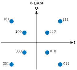
As in all other 2n-QAM schemes with n being an odd number, it's difficult to distribute the constellation points in a square lattice (compare in Figure 7). That has a negative impact on the BER performance; therefore, these 8-QAM schemes play a minor role in practice. Instead, usually 16-QAM is preferred for its double spectral efficiency at only slightly increased BER.
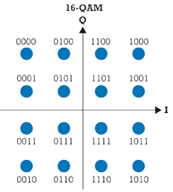
16-QAM. In this scheme, 4 bits are represented by one symbol. The 16 constellation points are distributed in a square lattice (see Figure 8). Typically, they are Gray coded; from one constellation point to every neighboring point, only one bit value changes. This way, if due to noise, a measured point is wrongly assigned to a neighboring point, the resulting bit error is kept to a minimum: 1 wrong bit.
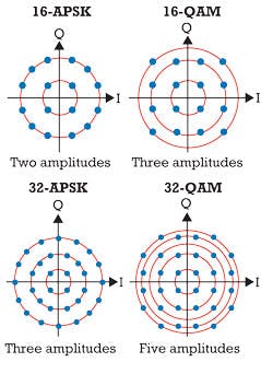
Amplitude- and phase-shift keying. In APSK, as its name implies, both amplitude and phase are modulated. It differs from QAM in that the constellation points are distributed on concentric circles in the I/Q-plane.
The concept was introduced for satellite systems where the RF power amplifiers show nonlinear behavior. Thus a scheme tolerant to nonlinear amplification was needed -- a concept with fewer amplitude states -- so that nonlinearities can be balanced more easily.
Comparing the constellation diagrams of 16-QAM and 16-APSK in Figure 9, in 16-QAM there are three amplitudes whereas 16-APSK has only two. In 32-QAM then, there are five amplitudes versus three in 32-APSK. Also note that the QAM rings are unevenly spaced, with some quite close together, which makes it even more difficult to compensate for nonlinearities.
In fiber optics, APSK can also be employed in nonlinear noise scenarios and for compensating nonlinear fiber characteristics. For speeds of 400 Gbps and beyond, however, 16-QAM is preferable because of its easier implementation and better optical signal-to-noise-ratio performance due to the larger distance between the constellation points.
Now you decide
The Table gives the characteristics of the most common modulation formats at 100 Gbps for non-polarization-multiplexed signals. If PDM is applied as well, the result is half the channel spacing or double the spectral efficiency.
Table: Characteristics of modulation formats at 100 Gbps without polarization multiplexing
Coding efficiency (bits/symbol)
Symbol rate (Gbaud)
Detection
Channel spacing (GHz)
Spectral efficiency (bits/sec/Hz)
Application area
OOK
1
112
Direct
200
0.5
Short distance (<200 miles)
DPSK
1
112
Direct
200
0.5
Short distance (<200 miles)
DQPSK
2
56
Direct
100
1
Metro (<500 miles)
QPSK
2
56
Coherent
100
1
Long-haul (>1,000 miles)
16-QAM
4
28
Coherent
50
1
Long-haul (~1,000 miles)
What already seems clear about the upcoming 400-Gbps and 1-Tbps transmission systems is that 16-QAM will play a major role. Multicarrier implementations will aggregate channels probably based on a new grid granularity of 12.5 GHz.
Additional importance will be placed on "Nyquist pulse shaping" to accommodate the increased amount of data in the existing infrastructure without any loss of information. We'll show in detail how that can be performed in the next article, which will be available soon on the Lightwave website, www.lightwaveonline.com.
Note: Figures in this article are courtesy of Oliver Funke, Michael Königsmann, Stephanie Michel, and Dr. Bernd Nebendahl.
STEPHANIE MICHEL is technical marketing engineer in the Digital Photonic Test Division of the Electronic Measurements Group at Agilent Technologies. This is the third article in a tutorial series on optical coherent transmission technology.
Archived Lightwave Issues

