Interferometric optical test and accurate component performance modeling
Traditional BER testing at the component and subassembly level is costly and time consuming. Optical vector analysis, a measurement principle based on coherent interferometry, provides not only fast and accurate measurements of loss and dispersion in components and subassemblies, but a practical and cost-effective means of predicting eye-opening power penalty and BER.
Dr. Brian Soller
Luna Technologies
Reduction of the capital expense of deploying high-data-rate DWDM optical networks will be an important driver in the recovery of the optical networking sector. The passive network elements that form the backbone of lightwave transmission systems (mux/demux, optical add/drop, optical crossconnect, etc.) require extensive testing to assure not only robustness but functionality. This is especially true for higher data-rate systems (≥10 Gbits/sec). The introduction of interferometric measurement instrumentation combined with the power of computational modeling can dramatically lower cost-of-test and hence the total cost of network deployment.
Integrated testing
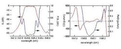
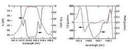
Components designed for high-speed networks are generally characterized by a set of four parameters: insertion/return loss (IL/RL), group delay or chromatic dispersion (GD or CD), polarization dependent loss (PDL), and polarization mode dispersion (PMD). Other metrics of more specialized interest, depending on the application, include group delay ripple (GDR), dispersion slope (DS), and second-order polarization mode dispersion (SOPMD). These parameters are measured as a function of optical wavelength at a resolution on the order of tens of picometers or less, depending on the application.
Measuring all of these parameters for a single component on multiple test stations requiring multiple reconnections would be far too time consuming and require too much capital equipment expense. This has pushed component manufacturers to look for integrated test solutions that can provide most of these measurements in a single instrument.
Most integrated test solutions, or all-parameter test stations, are modular in design. That is, they are a combination of multiple instruments and a tunable laser source that are sold in a package and arranged such that only one connection is required for testing over multiple parameters. While this solves the problem of having to connect and reconnect, it does not solve the problem of having to do multiple, separate tests to fully cover all of the parameters of interest.
Coherent interferometry
The introduction of widely tunable, mode-hop-free tunable lasers has enabled the introduction of coherent interferometry (CI) as a fast and accurate means by which to measure all of the linear parameters listed above. CI uses a continuously tunable laser source (TLS) to probe a device under test (DUT). The probe signal is mixed, using coherent detection, with a reference signal from the same source. The resultant signal contains amplitude and phase information about the DUT. The result is truly integrated test instrumentation that requires only one connection and a single scan of a TLS to fully characterize a passive component in seconds.
Interferometric test instrumentation not only provides the best combination of speed, accuracy and integration, it also provides the most fundamentally rigorous picture of how a component behaves when it is dropped into the network. This is because the interferometric technique does not rely on measuring different parameters separately. Rather, it is based on measuring a device's linear transfer function (LTF). For fiber-optic components, the LTF is a 2x2 matrix with four complex elements. In the frequency domain, it describes how the vector-electric-field that carries signal information propagates through the network. All of the information about how a component will affect a signal is contained in the LTF, including IL, PDL, CD, and PMD/SOPMD.
Given the standard set of measurement parameters for a component, predicting component performance in terms of eye-opening power penalty or bit error rate is not such a straightforward task. However, the rigorous component characterization provided by the LTF gives designers a fairly simple and accurate way of predicting how the component will function when dropped into a network. This is because given the spectrum of the input signal to a component, Ein(ω), the spectrum of the signal on the output side of the component, Eout(ω), is given by a multiplication: Eout(ω) = H(ω) Ein(ω), where H(ω) is the matrix LTF. Accurate performance prediction is therefore reduced to accurate characterization of the LTF and sufficient knowledge of the spectrum of the input signal.
CI offers the component manufacturer a fast, accurate, and rigorous testing solution that offers new ways of modeling a component's performance. This enables faster design times, more reliable systems, and lower-cost components.
Dr. Brian Soller is principle engineer at Luna Technologies Inc. (Blacksburg, VA). He can be reached at [email protected].

