Data-mapping techniques drive network design
The services that a carrier can offer depend on a number of protocol choices that are often implemented at the chip level-and equally as often poorly understood. A basic understanding of mapping is crucial, but cannot be limited purely to the protocol area. The location of mapping services in the network fundamentally affects the design and deployment of services. A look at a potential network implementation and how it might scale illustrates this point.
“Mapping” is merely the process of associating a set of values from one network with those of another network, or (for our purposes here) protocol. That happens in many places throughout the network.
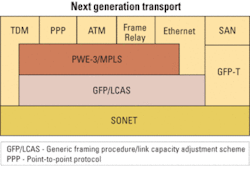
One popular Ethernet service is point-to-point, or E-line (using the conventions coined by the Metro Ethernet Forum), which enables two sites to interconnect their LANs. The network appears to the end users as one contiguous network. This is a simple and effective means of sharing corporate assets across sites. Another popular and more sophisticated Ethernet service is E-LAN, which enables multiple sites to hook into a private network without creating a large number of physical connections between sites, hence emulating a LAN across a wider network. Recently defined protocols enable these new services.A typical protocol stack necessary to implement these example services is shown in Figure 1. Working from the bottom of the stack, each layer performs a specific function. The SONET/SDH layer is endemic in the network and, though there may be some other native protocols at this level, it is far and away the most commonly installed protocol at the base of the network. It also happens to be a proven means to transport data, monitor network errors, and provide protection in the event of network failure.
The next layer up is the generic framing procedure (GFP) with virtual concatenation (VCAT) and the link capacity adjustment scheme (LCAS). GFP/VCAT was created to form a generic and efficient way to map (there’s that word) different upper-layer protocols into SONET/SDH. For instance, using VCAT it’s possible to fit one Gigabit Ethernet link very efficiently into a right-sized VCAT group (VCG), in this case STS-1-21v. Two of these links fit compactly in an OC-48/STM-16 link, removing the stranded bandwidth issue in legacy SONET/SDH network.
The next layer up is the pseudo-wire (PWE-3) and MPLS layer; for the sake of simplicity, we have put PWE-3 and MPLS in one layer. PWE-3 is designed to adapt a variety of different protocols into an MPLS frame so it can handle Frame Relay, Ethernet, and ATM traffic in one consistent manner, which helps with the migration of legacy networks. The MPLS portion is used to provision the end-to-end network and map the PWE-3-wrapped services into paths across the network with the correct quality of service (QoS) attributes.
Therefore, traffic gets wrapped in PWE-3 and routed using MPLS, which fits into SONET/SDH frames for error-free transport using GFP/VCAT. While it seems like a lot of layers, most of these layers are lightweight (low overhead), and each is responsible for a specific job.
The mapping at the GFP layer is central. In creating the best fit for a given service, GFP/VCAT creates the aforementioned VCGs, which are built up in low-order (LO) or high-order (HO) increments. LO is generally 1.5 Mbits/sec (DS-1), but there are other rates like VC-12 that are popular as well. HO is generally 51 Mbits/sec (STS-1), but other increments such as STS-3c or VC-4-Xv exist as well for SDH. For example, a 155-Mbit/sec HO VCG may be built up with three STS-1s, which is designated as “STS-1-3v.”
The inputs to the box that we want to map can be physical or virtual. By “physical” we mean an actual physical link-like a single 10-Mbit/sec Ethernet cable plugged into a port. A “virtual” input could be one or more flows on a given physical interface. Each flow can be identified by different tags obtained by classification of the concerned Layer 2 packet being mapped (e.g., VLANs on an Ethernet interface).
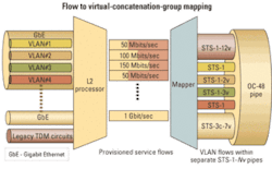
Our mapping job becomes one of selecting physical and virtual inputs and mapping them into one or more VCGs. The choices made here are reflected in the service offering. We use a flow to VCG mapping as shown in Figure 2.With this mapping, we can send each flow or VLAN to a separate destination; we also can assign a separate QoS to each flow as needed. While that seems great for the users, it is going to be a challenge for the equipment suppliers. If we assume there are eight Ethernet links attached to our box and each link has 20 VLANs, the result is 160 VCGs-which is well beyond the capability of much of the GFP silicon shipping today.
This mapping can happen in a number of places in the network. Let’s look at an example where a micro multiservice provisioning platform (MSPP)-also known as customer-located equipment (CLE)-is deployed on the customer premises. The CLE takes inputs from Ethernet, Frame Relay, and DS-1 services and maps them all through the protocol stack to a SONET/SDH uplink, which heads to the central office (see Figure 3).To follow the traffic path through the network, the VCGs will be created at the customer premises and traverse the metro aggregator rings. We will assume that at some point in the network the traffic will exit the TDM network to reach the Internet. That will happen at a large MSPP. Let’s look at two aspects of this scenario: provisioning and equipment performance.
Provisioning could be made quite easy in this scenario. Remember that in the stack we are using PWE-3 with MPLS. Thus, the control plane can create an end-to-end connection using a combination of MPLS and GMPLS. With MPLS, we can create a label-switched path that traverses the Internet portion of the traffic path. For the SONET (potentially DWDM also) portion, GMPLS allows us to set up the path for the VCGs through the transport network. That’s very interesting from an operations perspective, since there is the possibility of a very simple end-to-end provisioning scheme once the CLE has been installed.
Looking at the equipment, the CLE can be quite inexpensive, since it is focused on a narrow application set when compared to something like an access router. This new class of equipment is emerging rapidly and creates a smooth migration path from legacy protocols. Such equipment also provides a low-cost means to tap large and scalable amounts of bandwidth for services such as E-Line and E-LAN.
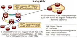
The MSPP connected to the core router has a larger task. To illustrate, let’s assume there is a 10-Gbit/sec link between the two and that this link is 50% utilized. We also assume that the average service to the end customers is 3-Mbit/sec Ethernet. This average service is twice the speed of a standard T1, which is still a very popular interface. The result is shown in Figure 4. The MSPP connected to the router deals with 1,667 flows or VCGs.From a network connection standpoint, that does not seem exceptionally large. But from a silicon standpoint, that presents a challenge. The largest GFP chips on the market today handle 128 VCGs. Thus, to scale to reasonably sized networks, at least one of several things should change: improved silicon, distributed network paths to share loads, and grooming and aggregation of VCGs.
Over time with service pricing dropping, users should be purchasing larger chunks of bandwidth, which will hopefully cause a drop in the average granularity. Of course, this pricing will draw even more customers into the network, so grooming VCGs off the SONET/SDH network and into the MPLS network will be important for maintaining manageability.
This example shows the impact on the overall network when a given stack is deployed for one topology. A change in deployment strategy would substantially affect the equipment required.
Let’s consider a change at the customer premises where we simplify the stack a bit. Our new (cheaper) CLE box will still use a SONET/SDH uplink and GFP/VCAT. It will be much less sophisticated when it comes to mapping and will handle a maximum of eight VCGs and simply map physical links to VCGs.
Two effects of this change are immediately noticeable. The first is that the operations staff can no longer use MPLS to provision the service all the way to the customer since our box does not support the PWE-3/MPLS features. The second effect is to burden the first edge MSPP that we hit in the central office with the job of mapping flows to VCGs. To do this mapping, the edge MSPP must first unpack the VCGs and examine the contents for flow identifiers (e.g., VLAN tags), then remap the flows into new VCGs. That takes a lot of effort and will add cost to the network equipment.
It is evident that the decisions about how protocols are mapped and their location in the network can have a significant effect on the network. It can change the cost of deploying services and affect the operations staff through provisioning mechanisms. Mapping features are generally built-in at the silicon level to take advantage of the economies provided from VLSI implementations. To optimize the silicon for the network applications, the chip providers must stay in close communication with the service providers.
The new generation of protocols now coming to market will simplify network operations, lower costs, and bring scalable bandwidth to customers. Understanding the details of these protocols and the mapping between them will help accelerate the deployment and improve carrier profitability and the customer experience.Dr. Partha Srinivasan is chief technical officer and Rajashree Mungi is principal architect at Parama Networks (Santa Clara, CA).


