Multiprotocol lambda switching comes together
MPlS is a suite of protocols that will enable optical-network equipment to speak the same language.
Luc Ceuppens
Calient Networks
Realizing the important role that photonic switches can play in data-centric networks, a number of leading router and optical-equipment vendors are collaborating to combine the control plane of Multiprotocol Label Switching (MPLS) with the point-and-click provisioning capabilities of photonic switches. The resulting protocols known as multiprotocol lambda switching (MPlS) will enable equipment in the service layer to dynamically request bandwidth services from the transport layer using existing control-plane techniques. Beyond simple advertising and establishment of optical paths through the network, MPlS includes performance information about the network. The service equipment at the edges of the photonic network will use this information to dynamically manage the available wavelengths in the photonic layer.
Photonic switching will radically change the way we build and use optical transport networks. Traffic-bearing beams of light will be switched transparently, independent of the bit rate, wavelength, and encoding scheme. Unlike the latest generation of optical-electrical-optical (OEO) switches, photonic switches switch photons rather than electrons. This unique capability effectively removes the "glass ceiling" displayed by OEO switches, which have difficulty supporting new encoding schemes and very high bit rates for large numbers of users. The same photonic switch can continue to provide transparent services to a user even if the traffic changes from SONET/SDH to Ethernet encoding, or as the traffic increases from 155 Mbits/sec to 10 Gbits/sec or beyond.The evolution to photonic networks will be gradual. Today's networks carry digital traffic on single wavelengths point-to-point across the network through multiple intermediate stages of optical-to-electronic conversion. Future photonic networks will multiplex and route wavelengths entirely in the optical domain, using wavelengths rather than timeslots as the basic element of transport.
In future networks, a best-of-breed optical solution may require the integration of next-generation and legacy equipment in a heterogeneous optical environment. These various network elements will communicate using a common standardized control plane. Beyond eliminating proprietary vendor "islands of deployment," this common control plane will enable independent innovation curves within each product class and faster service deployment with end-to-end provisioning utilizing a single set of semantics. Furthermore, using widely available Internet Protocol (IP) management tools and a single control plane for the transport and service-management layers will greatly simplify network operations.
Today's SONET/SDH transport-network infrastructure provides a guaranteed level of performance and reliability for voice calls and leased lines. But since 1995, we have witnessed a dramatic increase in data traffic, driven primarily by the explosive growth of the Internet. Last year, the amount of data traffic carried by the network surpassed voice. And data traffic will continue to outpace voice for years to come. The resulting need for increased capacity on the transport network has led to the deployment of DWDM systems, which significantly augment the bandwidth-carrying capacity of a single optical fiber, effectively creating "virtual fiber."
Yet, harnessing the raw bandwidth provided by DWDM to support the demand for multigigabit services has proven to be a real challenge within the scalability limits of today's network architecture. Today's data networks typically have four layers: IP for carrying applications, ATM for traffic engineering, SONET/SDH for transport, and DWDM for capacity. This architecture has been slow to scale, making it ineffective as the blueprint for photonic networks. Multilayer architectures typically suffer from the lowest common denominator effect where any one layer can limit the scalability of the entire network.
In today's competitive business environment, any technical strategy for network evolution must ultimately provide for competitive differentiation in service delivery. The ability to scale the network and deliver bandwidth and services when and where a customer needs it are absolute prerequisites for success.The limitations of the existing network infrastructure are hindering a movement to this service-delivery business model. A new network foundation is required, one that will easily adapt to support rapid growth, change, and highly responsive service delivery. The answer lies in an intelligent, dynamic, photonic transport layer deployed in support of the service layer.
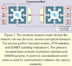
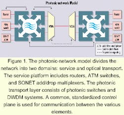
In general, the photonic-network model divides the network into two domains: service and optical transport (see Figure 1). This architecture combines the benefits of photonic switching with ad vances in DWDM tech nology. It delivers multigigabit bandwidth and provides wavelength-level traffic-engineered network interfaces to the service platforms. The service platform includes routers, ATM switches, and SONET/ SDH add/drop multiplexers (ADMs), which are redeployed from the transport layer to the service layer. The service layer relies entirely upon the photonic transport layer for the delivery of bandwidth where and when it is needed to connect to peer nodes or network elements. In this model, bandwidth is provisioned at wavelength granularity, rather than time-division multiplexing (TDM) granularities. To meet exponential growth rates, rapid provisioning is an integral part of the new architecture. While the first implementations of this model will support error detection, fault isolation, and restoration via lightweight SONET, these functions will gradually move to the optical layer.
Combining the bandwidth-provisioning capabilities of photonic switches with the traffic engineering capabilities of MPLS will allow routers, ATM switches, and SONET/ SDH ADMs to request bandwidth where and when needed.1 MPlS is designed to combine recent advances in MPLS traffic-engineering control-plane techniques with emerging photonic-switching technology to provide a framework for real-time provisioning of optical channels. That will allow the use of uniform semantics for network-management operations control in hybrid networks consisting of photonic switches, label-switched routers (LSRs), ATM switches, and SONET/SDH ADMs. While the proposed approach is particularly advantageous for data-centric optical-internetworking systems, it easily supports basic transmission services. MPlS supports the two basic network architectures-overlay and peer-proposed for designing a dynamically provisionable optical network.
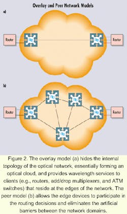
In the overlay model, there are two separate control planes: one in the core optical network and the other-often called user-network interface (UNI)-between the surrounding edge devices (see Figure 2a). There is minimal interaction between the two control planes. The edge devices only see light paths-either dynamically signaled or statically configured-across the core optical network, without seeing any of the network's internal topology. That is very similar to today's combined IP/ATM networks.
The disadvantage of an overlay network is that for data forwarding, a O(N2) mesh of point-to-point connections has to be established between the edge devices. Unfortunately, these point-to-point connections are also used by the routing protocols, producing an excessive amount of control-message traffic, which in turn limits the number of edge devices that can participate in the network. A single link-state advertisement (LSA) flooding event, for example, creates O(N3) messages on the point-to-point mesh.
In the peer model, a single instance of the control plane spans both the core optical network and the surrounding edge devices (see Figure 2b), allowing the edge devices to see the topology of the core network. Although a O(N2) mesh of point-to-point connections is still required for full connectivity between the edge devices, it is used exclusively for the purpose of data forwarding. As far as the routing protocols are concerned, each edge device is adjacent to the photonic switch it is attached to, rather than to the other edge devices. That allows the routing protocols to scale to a much larger network.
It is possible in a peer network to hide some or all of the internal topology of the optical network, if desired. That could be done by establishing permanent virtual-circuit (PVC)-like connections or forwarding adjacencies through the cloud and sharing them in the peer-to-peer topology exchanges with the edge routers. Conversely, when the overlay model is used, it is not possible to open parts of the optical network without segmenting the network into multiple subnetworks.
Rapid provisioning, routing, monitoring, and efficient restoration are paramount in photonic networks.
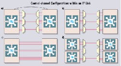
While several vendors are developing proprietary link-state and signaling protocols to enable automatic provisioning, these implementations are unlikely to work in multivendor deployments. A best-of-breed optical solution may require deployment of photonic switches in an optical network with next generation as well as legacy equipment. Thus, a common standardized control plane must be used for communication between the various elements. Over the last few years, the IP community has extended the IP control plane to connection-oriented technology, resulting in the development of a standardized suite of routing and signaling protocols under the umbrella of MPLS.Figure 3. Two photonic switches (a) are connected by a single Internet Protocol link using three DWDM devices and an out-of-band control channel. The out-of-band control channel could be a Gigabit Ethernet link between the two switches or even a separate IP network. The control channel (b) between two photonic switches is transmitted over an entire wavelength. Two photonic switches (c) are connected using direct fiber connections. The control channel is transmitted over a single fiber and the remaining bearer channel is used to switch either individual wavelengths or entire fibers. In the latter case, an entire fiber between a DWDM system pair, for example, could be routed transparently across a network of switches. The center DWDM system pair (d) is shared between two pairs of photonic switches. In this situation, an entire wavelength is used for the control channel between the upper two switches and another wavelength is used for the control channel between the lower two switches.
MPLS allows a variable-length stack of labels in front of an IP packet. LSRs forward incoming packets using only the value of the label on the top of the stack. This label, combined with the port on which the packet was received, is used to determine the output port and forwarding label for the packet. Connections established using MPLS are referred to as label-switched paths (LSPs). MPLS makes use of extensions to existing routing protocols such as open shortest path first (OSPF) and intermediate system to intermediate system (IS-IS) to exchange link-state topology, resource availability, and policy information required in the computation of LSPs. It also uses extensions to signaling protocols such as resource reservation protocol (RSVP) and label distribution protocol (LDP) to specify explicit paths for LSPs through the network and reserve resources.
There are several synergies between LSRs and photonic switches. Analogous to switching labels in an LSR, a photonic switch switches wavelengths from an input to an output port. Establishing an LSP involves configuring each intermediate LSR to map a particular input label and port to an output label and port. Similarly, the process of establishing an optical path involves configuring each intermediate photonic switch to map a particular input lambda and port to an output lambda and port. As in LSRs, photonic switches need routing protocols such as OSPF and IS-IS to exchange link-state topology and other optical resource availability information for path computation. Photonic switches also need signaling protocols like RSVP and LDP to automate the path establishment process.
Some modifications and additions are required to the MPLS routing and signaling protocols to adapt to the peculiarities of photonic switches. These adds and changes can be summarized as follows:
- A new link management protocol, or LMP, addresses issues related to link management in optical networks using photonic switches.
- An adapted OSPF2/IS-IS3 protocol advertises the availability of optical resources in the network (e.g., number of wavelengths, bandwidth on wavelengths).
- An adapted RSVP for traffic engineering allows an LSP to be explicitly specified across the optical core.
One characteristic unique to photonic switches is that the data-carrying (bearer) channels are transparent once they are allocated, meaning that, unlike traditional OEO switches, the control channel must be transmitted separately from the bearer channels. Figure 3 illustrates various control-channel configurations that can be envisioned within an IP link.
Photonic switches will be configured with IP links consisting of a single bidirectional control channel and a number of unidirectional user channels. The control channel and associated bearer channels do not have to be transmitted along the same physical medium. For example, the control channel could be transmitted along a separate wavelength or fiber, or along an Ethernet link between the two switches. An important consequence of physically separating the control channel from the associated bearer channels is that the health of a specific channel (control or bearer) does not necessarily correlate to the health of another channel on the link. That means traditional methods for failure detection can no longer be used, and new mechanisms must be developed to manage optical links.
LMP has been designed to address issues faced in managing links in optical networks with photonic switches.4
Although LMP assumes the messages are IP encoded, it does not dictate the actual transport mechanism used for the control channel. However, the control channel must terminate on the same two nodes that the bearer channels span. As such, this protocol can be implemented on any optical crossconnect, regardless of the internal switching fabric. A requirement for LMP is that each link has an associated bidirectional control channel and that the free bearer channels must be opaque (i.e., able to be terminated); but once a bearer channel is allocated, it may become transparent. Note that this requirement is trivial for optical crossconnects with electronic switching planes but is an added restriction for photonic switches.
LMP consists of four types of functions. A hello exchange is used to verify and maintain control channel and link connectivity between neighboring photonic switches. Link verification is used to verify bearer-channel connectivity and exchange label mappings. A link summary exchange is used to negotiate control-channel information, correlate link properties, and synchronize label matching. A fault-localization technique is used to isolate link and channel failures and initiate protection and restoration.
OSPF is a link-state routing protocol designed to run within a single area/autonomous system (AS). Each node in the area describes its own link states by generating LSAs. These LSAs are distributed to all nodes in the network using a process called reliable flooding. This information is used to create a link-state database, which describes the entire topology of the area/AS. Once a network has converged to steady state, all nodes will have identical link-state databases. As a result, any node in the network can use its link-state database to calculate the best route to any other node in the network.
The traffic engineering (TE) and MPlS extensions to OSPF4 add more information about links and nodes into the link-state database. This information includes the type of LSPs that can be established across a given link (e.g., packet forwarding, SONET/SDH trails, wavelengths, or fibers) as well as the current unused bandwidth, the maximum size LSP that can be established, and the administrative groups supported. That allows the node computing the explicit route for an LSP to do so more intelligently. The concept of a "derived link" has also been added. For example, if a wavelength LSP is established, it can then be advertised in the link-state database as a derived link, which is capable of supporting SONET/SDH or packet forwarding LSPs.
In the mid-1990s, RSVP was developed as a response to the increasing demand for Internet applications (such as video on demand) that require high levels of quality of service (QoS) from the network.5 Until recently, RSVP has been ignored for use in long-haul optical networks, due to scalability problems associated with the message overhead, the lack of mechanisms to efficiently provide traffic management, and the fact that it is based on unreliable messaging. But with the convergence of the Internet and telecommunication communities, extensions to RSVP are being developed to support MPLS and traffic engineering as well as address the scalability, latency, and reliability issues of the soft-state nature of RSVP. The RSVP-TE (RSVP with traffic-engineering extensions) proposal provides a number of extensions to establish MPLS LSPs.6 Proposed refresh reduction extensions address many of the drawbacks associated with the soft-state feature of RSVP for LSPs.7
Support for provisioning and restoration of end-to-end optical trails within a photonic network consisting of heterogeneous networking elements imposes new requirements on the signaling protocols. Specifically, optical trails will require small setup latency (especially for restoration purposes), support for bidirectional trails, rapid failure detection and notification, and fast intelligent trail restoration. The proposed modifications8 enhance the extensions of RSVP-TE6 and the refresh reduction draft7 to support the following functions:
- Reduction of trail establishment latency by allowing resources to be configured in the downstream direction.
- Establishment of bidirectional trails as a single process instead of establishing two uni-directional trails in a two-step process.
- Fast failure notification to a node responsible for trail restoration so that restoration techniques can be quickly initiated.
MPlS will combine existing control-plane techniques with the point-and-click provisioning capabilities of photonic switches to set up optical-channel trails and distribute optical transport network-topology-state information. The MPlS control plane will support various traffic-engineering functions and enable a variety of protection and restoration capabilities, while simplifying the integration of photonic switches and label-switching routers. Specifically, MPlS offers the following advantages:
- Faster service deployment with end-to-end provisioning utilizing a single set of semantics.
- Elimination of unnecessary network layers by enabling two-layer networking.
- Cost savings in network operations by using widely available IP management tools.
- Cost savings accrued in training by using a common control plane for optical- and service-management layers.
- Service creation enabled by common network knowledge of data and optical elements.
- Open-foundation protocol promotes innovation at the service layer.
- Promotes best-of-breed product selection for service providers.
- Accepted protocol enables independent innovation curve within each product class.
- Eliminates proprietary vendor "islands of deployment."
Now that the basic components are available to build photonic networks, intelligence needs to be added that enables the interworking of all the network elements (routers, ATM switches, DWDM transmission systems, and photonic switches). We envision a horizontal network where all network elements work as peers to dynamically establish optical paths through the network.
This new photonic internetwork will make it possible to provision high bandwidth in seconds, enable new revenue-generating services, and realize dramatic cost savings for the service provider.
Luc Ceuppens is senior director of product management for Calient Networks, a San Jose, CA-based photonic-switch vendor. John Drake, Jonathan Lang, and Krishna Mitra, also of Calient Networks, contributed to this article.
- Awduche, D., Rekhter, Y., Drake, J., and Coltun, R., "Multi-Protocol Lambda Switching: Combining MPLS Traffic Engineering Control with Optical Crossconnects," IETF work in progress, November 1999
- Katz, D. and Yeung, D., "Traffic Engineering Extensions to OSPF," Internet Draft, 1999.
- Smit, H. and Li, T., "IS-IS extensions for Traffic Engineering," Internet Draft, 1999.
- Lang, J.P., Mitra, K., Drake, J., Kompella, K., Rekhter, Y., Saha, D., Berger, L., Basak, D., "Link Management Protocol (LMP)," Internet draft, draft-lang-mpls-lmp-00.txt, March 2000. Work in progress.
- Braden, R., Zhang, L., Berson, S., et al, "Resource Reservation Protocol-Version 1 Functional Specification," RFC 2205, September 1997.
- Awduche, D.O., Berger, L., Gan, D.H., Li, T., Swallow, G., Srinivasan, V., "Extensions to RSVP for LSP Tunnels," Internet draft, draft-ietf-mpls-rsvp-lsp-tunnel-04.txt, September 1999.
- Berger, L., Gan, D.H., Swallow, G., Pan, P., Tommasi, F., "RSVP Refresh Overhead Reduction Extensions," Internet draft, draft-ietf-rsvp-refresh-reduct-02.txt, January 2000
- Lang, J.P., Mitra, K., Drake, J., "Extensions to RSVP for optical networking," Internet draft, draft-lang-mpls-rsvp-oxc-00.txt, March 2000.


