Standards for optical transport demand semiconductor solutions
Changes in the core infrastructure of the optical transport network will require the implementation of several functions in silicon.
Simon Keeton
Vitesse Semiconductor Corp.
The carrier landscape has endured rapid and fundamental change over the past decade. The traffic transported through the central office has evolved from voice traversing time-division multiplexed (TDM) circuit-switched networks to a mix of packet-based data and circuit-switched voice. This is placing new demands on the network architecture, such as a greater reliance on quality-of-service mechanisms, multiservice aggregation, and traffic management. As voice-over-packet technology becomes pervasive, this conversion will continue, invariably leading to an infrastructure almost entirely composed of data-centric networks.
Unfortunately, existing transport networks are based on SONET/SDH architectures that utilize voice-centric traffic models, which are largely unsuited to manage the growing flood of data. As network architectures continue to grow and adapt to these changes, standards for the optical transport network (OTN) are emerging that demand new semiconductor solutions. One example is the digital-wrapper-based implementation of the G.975 forward-error-correction (FEC) coding algorithm, Reed-Solomon (RS, 255,239). Other functions that require silicon hardwiring are client adaptation functions, such as mapping client signals into and out of optical channels and regeneration of "digitally wrapped" client streams.
The overall carrier-network architecture can be broken into two functional layers-the service layer and the transport layer. The service layer resides on top of the transport layer, which provides connectivity for the service layer elements.The service layer embodies functions that provide end users with services specific to their networking needs. Consequently, service layer elements enable the network to accommodate various data rates, protocols, and quality-of-service levels. The service layer is the "intelligence" in the network. It provides product differentiation and scalability to carriers deploying services.
The transport layer implements lower-level functions that enable connectivity between service-layer elements across the network. The key functions and metrics of the transport layer are capacity, reliability, and survivability. The transport layer is the backbone for the OTN.
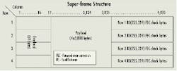
Two very similar protocols, SONET/ SDH remain the most common implementation of the network transport layer. Since SONET and SDH were initially developed to manage voice-centric communications, both utilize TDM to aggregate lower-rate tributaries to higher-rate line speeds.Figure 2. The lambda frame structure for short-haul interdomain interface with Reed-Solomon (255,239) forward error correction (FEC). In this structure, four 16-row "subframes" are grouped together to form a "super-frame," which provides 64x238 bytes of payload information, 64x16 FEC bytes, and 64 bytes of additional overhead.
It's no accident that the SONET baseline rate (STS-1) of 51.840 Mbits/sec efficiently accommodates a DS-3 voice circuit, the North American digital standard for up to 672 64-kbit/sec voice channels, or 44.736 Mbits/sec, which is the equivalent of a T3 line. Furthermore, the SONET frame period of 125 microsec (i.e., 8,000 frames per second) is specifically chosen to provide capacity for synchronous delivery of a single digital voice channel or DS-0 (8 bits x 8,000 times per second, or 64 kbits/sec).
The transport mix has changed significantly over the past decade-an epidemic process that continues today. Slow but steady growth of legacy voice-centric services, coupled with rapid expansion of newer data services, place greater demands on backbone infrastructure than ever before. What is needed is a multiservice transport infrastructure that can utilize a single OTN.
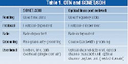
The OTN that fills this bill starts with service transparency, which, in turn, requires protocol and bit-rate independence. Another key attribute is the ability to reduce maintenance complexity by providing a single set of management mechanisms for all services based on a single transport protocol. The new OTN is preferably designed to minimize complexity and cost-a goal served well by reducing the number and specific types of network elements. Such an OTN provides virtual independence to clients, and thus could be deployed as the basis for the entire network.Today, DWDM technology enables OTN management to be based in the optical domain; clients are simply mapped to a specific wavelength for transport. Management is then based on the specific transport wavelength, not on client-specific information. Once a client is mapped to a wavelength, the transport mix is entirely transparent, and management is based on a high-capacity lambda rather than a TDM slot. A standards-based OTN allows network-to-network interconnections to be built and taken down transparently, or it enables modification of a client-service configuration in real time without affecting the transport infrastructure. Table 1 lists some key attributes of the new OTN versus traditional SONET/SDH.
As the network continues to evolve from voice to data-based transport, architecture changes are inevitable.
One likely change is to a mesh-based topology, an approach designed for a transport infrastructure based on uncommitted, shared bandwidth.
The mesh topology is well-suited to packet-based, terabit-class routing, which can minimize the cost and complexity of grooming and traffic management. The terabit routers sit on top of the OTN-based transport network. Routers form the service layer, while the OTN is the transport layer. Logical connection between routers are physically connected through the transport layer. Protection mechanisms in a mesh network rely on a diversity of available routing paths. This type of architecture also facilitates dynamic scalability based on subscription management and self-routing fabrics.
Carriers and OEMs alike are looking toward future deployment of a universal OTN. To date, the most appealing approach from either a cost or backward-compatibility standpoint is the proposed TDM "digital wrapper" protocol.Architectural details of the OTN are still being defined, but much of the groundwork has already been completed and is contained in the current version of the ITU-T G.872 recommendation. Some of the OTN's implementation details are contained in ITU-T G.709-a working draft that defines the optical network node interface for the OTN. This is the optical network-to-network interface for short-reach links up to 40 km.
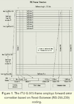
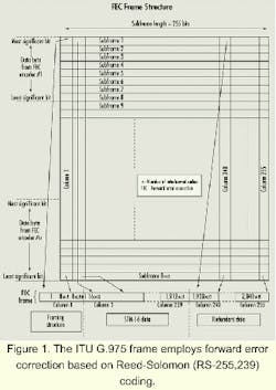
The G.709 network-to-network interface uses RS (255,239) coding, an FEC mechanism that is both protocol and rate independent, and provides the required overhead bytes for digital wrapper. This work represents the critical first step toward implementation of a standardized, universal optical transport technology.The initial proposals for a digital-wrapper standard roughly mirror the ITU G.975 frame (see Figure 1), which employs FEC based on RS coding. This algorithm results in a 16x255-byte optical channel frame that incorporates 16x16 redundant FEC check bytes to accompany each 16x238 bytes of payload, plus an additional 16 bytes of unused overhead. Taking this a step further, four 16-row "sub-frames" are grouped together to form a "super-frame," which provides 64x238 bytes of payload information, 64x16 FEC bytes, and 64 bytes of additional overhead (see Figure 2).
The proposed digital-wrapper overhead imparts many SONET/SDH-like features, yet is more universal in nature, allowing carriers to easily accommodate a wide range of speeds and feeds. Digital wrapper may represent the veritable Holy Grail of protocol-independent transport mechanisms for equipment vendors or carriers trying to win in the short-haul transport space. Unfortunately, the RS (255,239) algorithm isn't a beat-all, end-all solution for long-haul applications, where squeezing out the longest distance between transponders at minimal cost is key. In these cases, advanced-code, high-gain algorithms are more suitable.
The bottom line is the same functions and operations that occur in SONET/SDH overhead must occur in the optical transport network. In the SONET/SDH world, transport overhead is essential to providing operations, administration, maintenance, and provisioning as well as framing, bit-interleave parity calculations, trace identifiers, and protection switching. The 64 bytes of unused overhead resulting from FEC based on RS (255,239) are used for the digital wrapper, which implements these kinds of SONET/SDH-like functions.
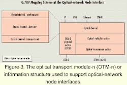
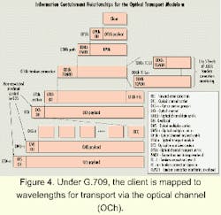
Under G.709, the client is mapped to wavelengths for transport via the optical channel (OCh) as defined in Figure 3 and Figure 4. The OCh consists of three parts: the OCh payload unit (OPU), the OCh data unit (ODU), and the OCh transport unit (OTU).The OPU is used to adapt client information for transport over an OCh and consists of both client information and the overhead information required for mapping to a client signal. The ODU consists of the information payload and the optical-data-unit overhead for management of the optical channel. The OTU adapts the ODU for transport over optical connections.
The OTU is slated for standardized vendor-to-vendor interconnections over inter-domain interfaces in the OTN. OTU connections can also be proprietary for connections within a manufacturer-specific subnetwork. The OTU consists of the ODU, OTU overhead, and the FEC bytes.
Based on performance requirements, building out the OTN mandates implementing a number of functions in silicon. One such function is the digital-wrapper-based implementation of the G.975 specification's FEC coding algorithm, RS (255,239).One of the key elements of the digital wrapper is interoperability for interdomain interfaces. When using the G.975 FEC algorithm with digital wrapper, it is important to ensure inter-operability between network elements. The ITU G.975 specification calls out specific details to enable this, but unfortunately leaves room for interpretation as well. A brief overview of the G.975 algorithm and operation is given in the sidebar, "A quick review of G.975 FEC RS (255,239) coding."
FEC coding in the digital-wrapper OTU uses 16-byte-interleaved codecs based on the RS (255,239) code. The RS (255,239) code has the following properties:
- q-ary code (non-binary).
- (n,k) block code, where:
n = codeword block length = q-1
k = information message block length. - Galois field (256) = GF(2m).
- Block length: n = 2m-1.
- n symbols made of m bits.
- Check symbols: n - k = 2t.
- t = error-correction capability.
- m = number of bits in symbol.
- Code rate = k/n (number of information bits per transmitted symbol).
Thus, a value of 8 for m and t, yields q = 256, n = 255 bytes, and k = 255 - (2)(8), or 239 bytes, as illustrated in Figure 5. The length of the code is one less than the size of the code symbols.
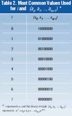
Algorithm generation of the RS (255,239) code is given in the G.975 specification from the generator polynomial and the primitive polynomial that defines this code. The generating polynomial of a t (8) error-correcting RS code of length 2m-1 (255) is given by:The ITU G.975 specification defines both the primitive and generator polynomials, but not the first eight a symbols, which in turn define the rest of the a symbols. Although not explicitly indicated in G.975, the use of different a symbols will render different implementations of the algorithm incompatible with one another. Thus, these values have been informally defined. Zero summarizes the common values used for the a symbols, which will ensure interoperability between G.975 equipment.
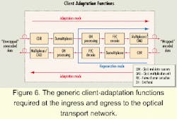
Clients are mapped onto the OTN, transported, and then demapped back to the original signal format. Accordingly, adaptation is necessary wherever the client's native signal enters or exits the network (see Figure 6).
Client adaptation covers a variety of functions. For example, tracing the steps at the ingress to the OTN, the process begins with clock extraction from the client signal. Next, serial-to-parallel demultiplexing may be required if processing at a speed lower than the line rate is needed. This is likely to include some client-specific overhead processing, such as SONET/ SDH/ Gigabit Ethernet, or accumulating data for subsequent performance monitoring.
The client signal is then encoded using the FEC algorithm, and the digital-wrapper overhead is added to the frame. Finally, lower-rate parallel signals are multiplexed to higher-rate serial signals if required, and the digital-wrapper signal is transmitted. At the OTN egress, the client signal is reacquired by executing the previously described operations in exactly the opposite order.
Another universal function that requires hardwired logic is regeneration (loopback) of the incoming digitally wrapped client signal. This process also requires some performance monitoring functionality before regeneration and transmission. Signal regeneration includes many of the same steps required for client adaptation, including clock extraction, demultiplexing/multiplexing, and FEC decoding/encoding.Digital-wrapper-specific overhead processing is also required for regeneration, which includes monitoring FEC overhead bytes in incoming client signals and inserting information into outgoing FEC overhead bytes. This process entails monitoring OTU and ODU overhead totaling six tandem connection-monitoring fields, a section-monitoring field, and a path-monitoring field. Each field has subfields for trail-trace-identifier and bit-interleaved-parity (BIP-8) subfields. BIP-8 error checking is accomplished by calculating the parity over the bits of the OPU and then inserting the value into the BIP-8 field location in the overhead of the next, following frame. In order to maintain correct BIP-8 calculations during the regeneration process, the payload information and overhead information must remain aligned to the same position through the entire process, since the BIP-8 calculation is performed over specific bit locations.
One area in current development is client adaptation for multiple services. Specifications for mapping clients into the OPU have evolved significantly to include various data rates and protocols. Mapping schemes for SDH clients currently in development include STM-16 (2.5 Gbits/sec) into OPU1, STM-64 (10 Gbits/sec) into OPU2, and STM-256 (40 Gbits/sec) into OPU3. In addition, mapping the STM-N (N = 16, 64, 256) signal into an OPUk (where k = 1,2,3) can be accomplished using two different modes, asynchronous or bit synchronous, based on the same generic OPUk frame structure.
Mapping schemes for other clients are currently being defined, including ATM cells, generic-frame procedure frames, null clients, pseudo-random bit-sequence test signals, and non-specific client bit streams. In the near future, multiplexing ODUs within the OTN is an issue slated for analysis. When defined, this capability will enable TDM hardwired aggregation of lower-rate ODUks into higher-rate ODUks in silicon. For example, four ODU1s could be mapped into an ODU2, 16 ODU1s into an ODU3, or four ODU2s into an ODU3, etc.
Thanks in large part to the efforts of individuals who make up the ANSI and the ITU-T standards bodies, the ambition of developing OTN specifications continues to move forward. The OTN holds the promise of service transparency, protocol and bit-rate independence, generic performance monitoring and maintenance mechanisms (i.e., digital wrapper), and ability to minimize cost and complexity.
Simon Keeton is product marketing manager at Vitesse Semiconductor Corp. (Camarillo, CA) .
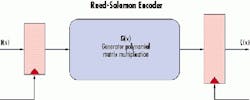
Thus, the higher the code rate, the lower the redundancy data or overhead of the code. The encoding process (see Figure) involves reception of the information vector I(x) and multiplying it by a generator polynomial G(x). The generator polynomial is derived from the selected RS code (n,k) with a desired error correction performance, t. The resulting RS codeword C(x) contains more symbols than the information vector I(x) due to the additional redundancy data (2t symbols).
