Gigabit Ethernet: Going further than thought possible
In certain situations, network designers can build a system capable of transmitting data over significantly longer fiber lengths than those listed in the Gigabit Ethernet standard.
ERIC LEICHTER, Corning Cable Systems
The push is on for transmitting data at higher speeds in premises systems. Many of these networks are currently being built or upgraded to support a need for increased bandwidth. With higher data rates, system operators are naturally concerned about the ability of the physical layer to support their networks.
To demonstrate how typical connectors and several cabled multimode-fiber types would fit into a Gigabit Ethernet (GbE) system, Corning Cable Systems conducted testing in conjunction with Anixter, a large telecommunications equipment distributor. At the Anixter Levels Laboratory, transceivers were used to send data at GbE speeds over cabled optical-fiber links terminated with MT-RJ connectors. GbE systems (1000Base-T) are designed to run at speeds that are 100 times faster than standard Ethernet (10Base-T) and 10 times faster than Fast Ethernet (100Base-T) systems.The MT-RJ connector is the most common small-form-factor (SFF) connector type placed in today's private-network systems. The "Optical Fiber Cabling Components Standard" (TIA/EIA-568B.3) allows for SFF connectors as well as SC duplex connectors. The MT-RJ does not have the years of system use, however, that the widely deployed SC duplex connector has experienced. Although MT-RJ connector performance conforms with the TIA/EIA-568B.3 specified insertion-loss maximum value of 0.75 dB per connector pair, there may be some concern as to how this connector will perform in a system running GbE.
During the testing, data was successfully transmitted at GbE speeds while significantly exceeding the system lengths and link-loss values specified in the IEEE standard, 802.3z, "Carrier Sense Multiple Access with Collision Detection Access Method and Physical Layer Specifications." This standard is commonly referred to as the Gigabit Ethernet standard.
A transceiver generated the data frames and measured the throughput. The data was transmitted through a switch, which was a typical example of equipment used in a LAN system and within the specifications outlined by the IEEE 802.3z standard. These units incorporated GbE cards using vertical-cavity surface-emitting laser (VCSEL) technology.
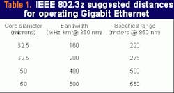
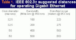
Data frames were transmitted and tested at the short wavelength, 850 nm. Test data was sent out over a range of frame sizes. The criterion for passing the test was 100% data received at each frame size. Any performance of less than 100% indicated lost data and would have been considered a failure during this testing. As an optical receive parameter, the Gigabit Ethernet standard recommends a bit-error rate of less than one part in 1012.As shown in Table 1, IEEE 802.3z specifies the acceptable length of each optical-fiber link. If the system link does not exceed the specified length or insertion loss, the system will be able to successfully support GbE speeds. These values for length and insertion loss are specified independent of connector type.
Exceeding these distance values does not automatically indicate that a system will fail at gigabit speeds. These values are merely fail-safe numbers derived using the worst-case scenarios of the GbE model. The IEEE 802.3z states, "a transceiver that exceeds the operational range requirement while meeting all other optical specifications is considered compliant." It allows for higher grades of fiber and variations in the end electronics to translate into successful transmission over longer distances.
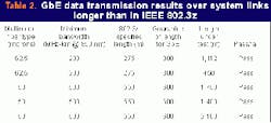
Link lengths longer than those specified in Table 1 would be unusual in a typical intrabuilding link. Exceeding these distances is more likely to happen in a campus environment-going from one building to another. Operating GbE at these longer distances would seem to necessitate the need for singlemode fiber. Multimode fiber, however, may also be a viable solution. To demonstrate this point, testing was conducted for links well beyond the lengths specified by IEEE 802.3z.The cables under test incorporated one of two types of fiber: 62.5/125-micron multimode fiber that has a manufacturer specification for GbE operation up to 300 m at 850 nm when deployed in accordance with IEEE 802.3z or 50/125-micron multimode fiber that is specified for Gigabit Ethernet operation up to 600 m. The interconnect cables containing the fibers used in these links were taken from standard stock and not selected for high performance within their grade. Table 2 shows a sampling of these tests.
Note that the data does not represent maximum system lengths for each fiber type. Due to the cable lengths available for this experiment, it was not practical to determine exact failure points. The goal of these tests was merely to show that in some situations, such as using high-grade fiber, a system could be built that is capable of transmitting data over significantly longer lengths than those listed in the standard.
Along with the varying lengths of each link, there was also a variance of link loss and number of connector pairs. The 50-micron multimode-fiber link that was able to transmit data over the length of 2,160 meters contained two connector pairs and had link attenuation of 6.4 dB and 6.9 dB for fibers 1 and 2, while the 1,400-meter link contained 13 connector pairs and had link losses of 6.8 and 6.7 dB.
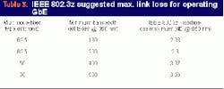
Constructing a system beyond the maximum lengths stated by the IEEE 802.3z standard increases the probability of exceeding the link-loss maximum imposed by the standard. The loss of each link comprises two components: the attenuation of the optical fiber and insertion loss of the connector pairs. The total loss can consist of any percentage of connector or optical-fiber loss. Table 3 outlines the recommendation according to fiber type and grade.
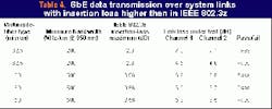
Again, these values are conservative and considered worst-case values; exceeding them does not automatically doom a system to failure since a lot of potential power loss is reserved as a "power penalty." That will allow for future changes in the system, such as transmitter degradation or the addition of a crossconnect. As shown in Table 4, the links under test had link-loss values that exceeded the IEEE 802.3 recommendation.The loss of each link in Table 4 comprised the attenuation from long lengths of cabled fiber and insertion loss of the connector pairs. The attenuation caused by excessive lengths may not always cause a system failure, but what about the connectors?
The Gigabit Ethernet standard does not specify a number of connector pairs for a system link. Instead, 802.3z specifies the insertion-loss values shown in Table 3. It would be difficult to place a high number of connector pairs into a system and stay below these insertion-loss values with every system link.
The most common path between electronics in a LAN system is short and direct. The typical link between two transceivers contains just two or three connector pairs and the length of fiber. With this basic setup, it is unlikely that a link with MT-RJ (or duplex SC) connectors would cause the link to exceed the insertion-loss value set in the standard.
As an example from Table 4, the standard allows a total link loss of 2.6 dB for 62.5-micron fiber with a specified bandwidth of 200 MHz-km at the 850-nm wavelength. In fact, if a connector-pair loss of greater than 0.75 dB (as specified by TIA/EIA-568B.3) is not allowed, no violation of this insertion loss can occur with only two connector pairs unless there is excessive fiber loss. The MT-RJ connector can easily meet this requirement.
Some systems may have more than two or three connector pairs. In most cases, that is unlikely to cause the high loss necessary to cause a system failure. For testing purposes, links were constructed with various numbers of connector pairs to see how that would affect system performance.
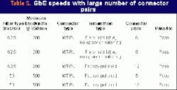
The cables were terminated with two different types of MT-RJ connectors. Some links were pre-terminated with factory-installed epoxy/polish-type MT-RJ connectors. These examples were typical of pre-terminated links that could be quickly installed as intrabuilding runs with little installation effort. Other cables were terminated onsite with a field-installable MT-RJ connector type that does not require epoxy, curing time, or polishing. Without these time-consuming steps, the preparation of each connector could be accomplished in about one minute. As with the optical-fiber cables, these connectors were standard products drawn from stock. To test a variety of fiber types and connector pairs, many combinations were assembled. Table 5 shows some of these combinations.The MT-RJ connectors performed well in each experiment. Transmitting 100% of the data frames, the links with factory-polished MT-RJ connectors and with the field-installable MT-RJ connectors exhibited acceptable gigabit-speed operation. The use of eight field-installed connector pairs in one link surpasses the expected design of most systems. Links with 12 or more factory connector pairs would be even more extreme cases. Hence, when designing a system with a typical number of connector pairs, there should be no concern with operating at Gigabit Ethernet speeds over a system incorporating the MT-RJ connector.
These links were not tested to failure for insertion loss or for a maximum system length. There are too many system variables to characterize the exact failure point of a passive optical-fiber system. Each transceiver on the market has different operating characteristics, and optical fibers of different grades or from different manufacturers may also affect the system performance. The large number of variables clearly explains why the standard is designed with very conservative recommendations. This testing has shown that following the standard under normal conditions assures a GbE-capable solution.
The testing did demonstrate that the recommended lengths and link-loss values stated in the standard could be significantly exceeded. Tables 2 and 4 show that a system may be able to operate well beyond the values specified by the standard. A system designer may be able to plan for longer system lengths when using high-grade optical fiber. Several manufacturers offer fiber types with specified GbE performance above the limits put forth by the 802.3z standard. MT-RJ products can also be safely designed into a GbE system.
This news is good for today's expanding systems. The Gigabit Ethernet test results suggest more flexibility and indicate that a system built with today's connectors and optical fibers will be functional for a long time.
Eric Leichter is an applications engineer at Corning Cable Systems (Hickory, NC). He can be reached at [email protected].
Lightwave is a monthly international publication focusing on fiber optics and optoelectronics, the technologies driving the growth, convergence, and improved performance of telephony, computer communications, and video. Lightwave provides technology news as well as applications and product information for corporate and technical managers and staff engineers. Lightwave's editors emphasize analysis and interpretation in their reports on the technological impact of fiber-optic components, systems, and networks in these markets.
