Laser eye safety for DWDM networks
With transmission powers and the number of wavelengths increasing, the difficulty of operating optical-networking systems safely becomes significantly more complex.
BETH KOELBL, NuLight Optics, CURTIS HILL, Bell Atlantic, and JEFF YOUDES, Southwestern Bell Corp.
As the deployment of all-optical DWDM networks quickly evolves, the possibility of personnel being exposed to harmful amounts of radiation increases, unless user organizations establish adequate protection and controls. This is not only due to increases in the output powers of C-band (1,530-1,560 nm) erbium-doped fiber amplifiers (EDFAs), but also due to the commercial availability of L-band (1,570-1,610 nm) EDFAs and Raman amplifiers (RAs) operating over the entire EDFA bandwidth. With the advent of bi-directional systems and amplifiers in the S+ (1,450-1,480 nm) and S (1,480-1,530 nm) bands, personnel will not only have to be concerned with high optical powers, but also with the fact that emissions can (1) be over a wide range of wavelengths and (2) originate from both directions.
Commercial DWDM systems and network configurations have evolved to operating powers well beyond 17 dBm. In accordance with the American National Standards Institute (ANSI) Z136.2 and the International Electrotechnical Commission (IEC) 60825-2 standards, if these systems do not have an automatic power reduction/ automatic shutdown (APR/ASD) feature, the user organization will have to implement numerous costly programs such as a designated laser safety person, extensive safety training, eye examinations, and administrative programs. These requirements are well beyond general laser safety training, labeling, and the usage of eye protection when viewing emissions with a microscope or eye-loupe.1, 2
Let's look at the current laser safety standards with respect to high-powered DWDM systems, user organization responsibilities, and suggestions to ensure a safe working environment. Note that even though we focus solely on 1,550-nm emissions, due to the usage of EDFAs and RAs in this wavelength region, the same safety principles will apply to 1,310-nm systems, but at lower power levels.
ANSI publishes the standards that are followed by the U.S. Food and Drug Administration and that are, in turn, followed by the Occupational Safety and Health Administration and other legal entities in the United States. In accordance with the ANSI Z136.2-1997 document ("American National Standard for Safe Use of Optical Fiber Communications Systems Utilizing Laser Diode and LED Sources"), the following are the definitions for the Service Group (SG) classifications for optical-fiber communication systems (OFCSs).1 Note that laser module emissions are classified as an ANSI Class 1, Class 2, Class 3a, Class 3b, or Class 4, if it is within the accessible emission limits (AELs).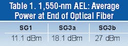
SG1: The total output power of the OFCS is less than the AEL for Class 1 and there is no risk of exceeding the maximum permissible exposure (MPE) (ANSI Z136.2) when viewing the end of a fiber or connector with a microscope, an eye-loupe, or with the unaided eye. Thus, the system is not considered to be hazardous with or without eye aides.
SG2: An OFCS that emits energy at wavelengths between 400- and 700-nm and is potentially hazardous when it is viewed for more than 0.25 sec with the unaided eye.
SG3a: An OFCS that may be hazardous when viewed with a microscope or an eye-loupe but is not hazardous when viewed with the unaided eye.
SG3b: An OFCS that may be hazardous when viewed with the aided and unaided eye, but its scattered radiation and diffuse reflections are not considered hazardous.
SG4: An OFCS in which direct and indirect viewing is considered hazardous.
In computing the AELs for a 1,550-nm OFCS, a typical mode-field diameter (MFD) of 11 microns was used. The computed AELs are in Table 1, in accordance with ANSI Z136.2-1997 for the case in which the OFCS has no APR/ASD.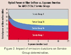
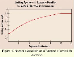
Note that these figures assume a viewing duration of >10 sec. If the time duration is less, then the heating spot formed on the eye is smaller. Thus, the amount of power from the fiber end can be greater. The ANSI Z136.2 standard accounts for this by varying the "affected spot" or limiting aperture (d0) for hazard evaluation as a function of emission duration. This relationship for the 1,400- to 2,600-nm region is shown in Figure 1 and Table 2.
The impact of these durations on SG determination is shown in Figure 2. From this graph, it is evident that any optical emissions >27 dBm (500 mW) are in SG4, regardless of the APR/ASD "reaction time." If an OFCS can perform an APR/ASD function within 0.1 sec, it can be classified as an SG1 system up to the >27-dBm power level. However, if the APR/ASD function fails, then the equipment can be within the SG3b category if the power level is between 18 and 27 dBm. In this case, emissions may be harmful to the eye.
From the IEC 60825-2, "Safety of laser products, Part 2: Safety of optical fibre communication systems" (4.4.1), the "Hazard Level" is defined as "The potential hazard at any accessible location within an optical-fiber communication system. It is based on the level of optical radiation which could become accessible in reasonably foreseeable circumstances, e.g., a fiber cable break. The methods for determination of compliance with the specified radiation limit values are the same as those described for classification in the IEC 60825-1."3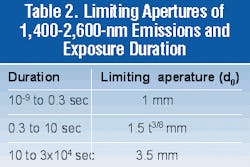
The IEC 60825-1 document is for the safety of laser devices and modules, but not for an entire optical-communications system. Note that the IEC 60825-1 document has the same definitions for the 1, 2, 3a, 3b, and 4 categories as the ANSI document.
The IEC 80625-2, Amendment 1 mentions that Hazard Level evaluation may be different from the IEC 80625-1 classification.2 This may be due to:
1. The IEC 60825-2 standard also has a "k x 3a Hazard Level" that is in between the 3a and 3b levels. "For purposes of the k x 3a Hazard Level evaluation, Class 3a AEL table is used and the minimum measurement distance shall be increased to 250 mm (25 cm) from the apparent source and the time base used shall be 10 sec, provided longer viewing durations are not reasonably foreseeable." Note that for other hazard assessments, the distance is 100 mm (10 cm).
2. Also, in IEC 60825-2 (4.5), the installation requirements with respect to each location are:
- Unrestricted locations-Hazard Level 1, 2, or 3a.
- Restricted locations-Hazard Level 1, 2, 3a or k x 3a.
- Controlled locations-Hazard Level 1, 2, 3a, k x 3a or 3b.
- No optical-fiber communication system shall have locations with a Hazard Level 4.
- The IEC 60825-2, Amendment 1-1997 (D.3.1) lists typical fiber-optic installations at these locations:
a) Controlled: cable ducts, street cabinets, manholes, and dedicated and delimited areas of network operator distribution centers.
b) Restricted: secured areas within industrial and business/commercial premises not open to the public; general areas within switching centers; delimited areas not open to the public on trains, ships, or other vehicles; overhead fiber-optic cables and cable drops to a building; and optical test sets.
c) Unrestricted: domestic premises, industrial or business premises, and any public areas.
3. An automatic power reduction (APR) can be used within a system. For optical-fiber communication systems with APR, the Hazard Level will be determined by the normal level of power in the fiber and the speed of the automatic power reduction.
4. Results from fault analysis in IEC 80625-2 are different from single fault analysis in IEC 80625-1. Tests shall be carried out under reasonably foreseeable fault conditions.
In accordance with IEC 60825-2, Amendment 1-1997, the basic Hazard Levels for a 1,550-nm emission from an 11-micron MFD fiber (no automatic shut-down) are:
- Hazard Level 1 = 10 mW (10 dBm).
- Hazard Level 3 = 50 mW (17 dBm).
- Hazard Level k x 3 = 54 mW (17.3 dBm).
- Hazard Level 4 = 500 mW (27 dBm).
Note that the Hazard Levels are slightly lower or the same as the AELs of the ANSI service groups, with the addition of the k x 3a Hazard Level.
In Amendment 1 (D.5.3.2) for connectorized systems, it is assumed that "human accessibility to the energized fiber would not occur until 1 sec after the disconnection. As a result, the power- reduction duration specified would be increased by 1 sec for this application."2 This enables the power limit for the Hazard Level to be increased in a similar manner as indicated in Figure 2 for the ANSI Z136.2 standard.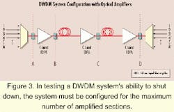
An extensive reliability analysis on the APR circuitry is given in Amendment 1; however, it is mentioned that, "No system is 100% fail-safe since there is always a nonzero probability that failures will occur." Amendment 1 also mentions that "a circuit design with less than 500 FITs is achievable, which translates to an occupational risk of less than 5 HITs, which the U.K. health and safety executive considers an occupational risk of less than 5.43 HITs for accidents to be 'trivial.'"2
Since each vendor's equipment operates differently and it is the user organization's responsibility to ensure that all accessible emissions are safe, the user organization should ensure that the DWDM system is safe. With SG1 ("eye safe") radiation emissions, the user organization needs only to inform personnel about general eye safety procedures. With SG3a (unaided eye okay, aided eye hazardous), the user organization needs to inform personnel and ensure everyone's eyes are protected when using eye-loupes, microscopes, etc. When "Service Group 3b or SG4 systems are serviced, management (employer) is responsible for the establishment and surveillance of the appropriate control measures."1
The ANSI and IEC standards enable manufacturers to use an ASD or APR mechanism to reduce the hazard level, since eye injury is dependent on the radiation-exposure duration. Thus, high-powered DWDM systems (>17 dBm) may be designated as be ing within the ANSI SG1 or 3a/IEC Hazard Level 1 or 3a categories even though their operating powers are significantly higher. All of the standards emphasize that the user organization is responsible for the potential safety hazard, including the reliability of the APR/ASD mechanisms and implications if the APR/ASD system can be manually or remotely overridden.
For DWDM systems operating at powers >17 dBm, the following items are suggested features and practices for a safe work environment:
- Use eye protection when working with eye-loupes, microscopes, and other directly magnifying instruments.
- DWDM systems should have APR/ASD functions.
- Limit all APR/ASD override features to very-well-trained personnel only or disable the feature permanently.
- Test the equipment's ability to perform its APR/ASD operation in your "worst case" proposed network configuration (i.e., the one with the most amplifier interfaces). (See the "APR/ASD Testing" section for more details.)
- Evaluate the FIT rates of all critical components for the APR/ASD feature along with acceptable legal FIT rates in the jurisdiction of operation.
- Ensure that disconnection of connectors with high output powers on "active" equipment bays (i.e., ones that contain laser sources) can only be performed through enabling some type of latch mechanism, which disconnects the entire laser source card from the backplane (i.e., powers it down).
- Use built-in external monitor ports (where only a small amount of power is tapped off) for signal quality-level observation. Also, this port can be used to check the system "health" with an optical time-domain reflectometer without disrupting service.
- At optical crossconnect, fiber distribution frame, patch panel, and other "passive" equipment locations, it cannot be ensured that the manufacturer has put any safety labels or precautions at the ports, since these pieces of equipment may come from a different manufacturer than the one that produced the DWDM terminal or optical add/drop multiplexer equipment. Prior to equipment deployment, the user organization must affix labels and administrate a plan to restrict access to only authorized personnel and with eye protection. Possibly a "shuttered" connector or a type of indicator that warns personnel of high radiation may also lessen these safety hazards.
- When performing splicing in the field, especially for fiber ribbon fusion splices, it may eventually be necessary to have some sort of machine that performs both the cleaving and the fusion splice without the risk of technicians being exposed to a high level of optical power. It is when the fibers are cleaved that the emissions pose the greatest hazard. The risk is reduced when the fiber(s) are fractured or broken.
- In systems where a high-powered signal may be broadcast, a service provider may not want the entire system to shut down due to a failure on one branch of a splitter. Thus, access to these splitters must be controlled if the output powers are >17 dBm.
For DWDM products operating at >17 dBm, most vendors use some form of APR/ASD. However, they have slightly different ways of implementing these safety mechanisms. The DWDM system should automatically reduce power or shut down if the input power to an optical amplifier is too low or a fiber breaks or is cut or if a connector is disconnected.
Some methods used to determine the presence of these scenarios are:
- Detecting low input power coming into an optical amplifier through a monitor port and using it to control the optical amplifier as well as to report this information back to the terminals on the optical supervisory channel (OSC).
- Detecting a low input power at the receiver and sending this information over the OSC to the terminal transmitter to get the appropriate optical amplifier to turn off or reduce power.
- Detecting a high reflectance coming back to the output port of an optical amplifier and likewise control the optical amplifier and report back via the OSC.
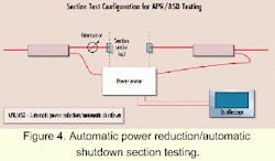
The input power level that triggers the APR/ASD, the output power level before, during, and after the APR/ASD; and the reaction time of the system are measured. Since all equipment vendors use different methods of detecting scenarios that require APR/ASD, it is necessary to perform this testing near both end-terminal locations (sections AB and CD) and at least one optical amplifier site (section BC).
The precise methods in computing the actual hazard before, during, and after the APR/ASD procedure are described in ANSI Z136.2 and IEC 60825-2. Note that the current ANSI Z136.2 requirements are shown in Figure 2 for a 1,550-nm emission from an 11-micron fiber, for quick reference.
Next, a test of the operation of the APR/ASD feature when associated card units are removed (instead of attenuating the power) should be performed in the same manner as discussed previously.
As networks evolve to include high-powered C-band, L-band, and Raman amplifier-based products, the optical power level per fiber increases. This in turn increases the need for precautions to be taken to ensure a safe work environment for installation, operations, and maintenance personnel.
To maintain this safe working environment, network operators must use multiple features and precautions, such as APR/ASD, interlocks, safety connectors, etc. Also, it is important that the performance and reliability of these network features be checked for user-specific deployment scenarios. If a network is unable to reduce power or shut down quick enough, then potentially hazardous emission levels may be present.
Beth Koelbl currently consults for NuLight Optics (Fairfax Station, VA). She can be reached at [email protected] or http://home. att.net/~nulight. Curtis Hill is a senior specialist for Bell Atlantic. Jeff Youdes is a corporate manager of new technology introduction for Southwestern Bell Corp.
Thanks to the National Telecommunications Alliance, Doug Teller of Bell South, Booker Tyrone and Bernie Cross of Southwestern Bell, and Jason Ackerman of US West for their invaluable inputs.
- American National Standards Institute, "American National Standard for the safe use of Optical Fiber Communication Systems Utilizing Laser Diode and LED Sources," New York, ANSI Standard Z136.2, 1997.
- International Electrotechnical Committee, IEC 60825-2/Amendment 1 "Safety of Optical Fibre Communications Systems," 1997-12.
- International Electrotechnical Committee, IEC 60825-1 "Safety of laser products-Part 1: Equipment classification, requirements and user's guide," 1998-01.