10-Gigabit Ethernet devices 'stressed' by new test
There's one segment of the telecommunications industry that isn't afraid of a little stress. Ratified in May, the IEEE 802.3ae specification describes a new method for testing 10-Gigabit Ethernet (10-GbE) devices using a degraded or stressed signal to mimic worst-case conditions and thereby ensure the easy plug and play of 10-GbE devices across a wide vendor space.
"There's a real straightforward reason for the new standard: interoperability," asserts Bruce Nyman, chief technology officer of JDS Uniphase's Instrumentation Division (Ottawa, Ontario). "My module has to work with your module so we have to agree on the worst-case performance that I might send you and that you agree to work with."
"All the early products out there at the moment may work with each other, and they may work fine with each other," adds Bob Noseworthy, 10-GbE consortium manager at the University of New Hampshire's Interoperability Lab (Durham, NH). "But somebody in the future could build a part that is compliant transmitter-wise to the specification, but because of some permutation of variables, it ends up not working with existing products. If you could exhaustively test your receiver, then you're closing the loop on potential future pitfalls."
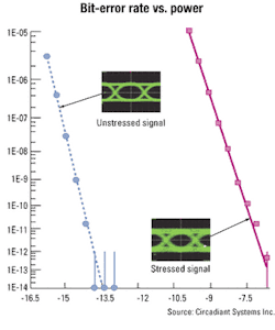
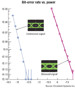
The new specification takes its cue from the data communications world, in which components are tested with degraded signals that more closely represent what the device might see in the field. The Stressed Receiver Conformance Test achieves the worst-case scenario by specifying a poor extinction ratio and adding multiple stresses in concert, including intersymbol interference (ISI) or vertical eye closure, sinusoidal interference, and sinusoidal jitter. The test specifies that the bandwidth of the signal be restricted, which is achieved by running the electrical data signal through a low-pass filter before going to the laser. "Essentially, it's going to attenuate the high-frequency components of the signal and cause the eye to close a certain amount vertically," says Greg LeCheminant, product marketing engineer at Agilent Technologies (Palo Alto, CA). Also known as the Vertical Eye Closure Penalty, the application of the low-pass filter achieves two-thirds of the required eye closure. The remaining stress is achieved through the addition of sinusoidal interference, which causes the eye to close an additional amount vertically but will also cause some closure horizontally, thereby replicating a certain magnitude of jitter.
Finally, the receiver under test must be able to recover the signal error-free when a certain amount of sinusoidal or phase jitter is added to it, as specified by the standard. "You run the jitter all the way out to about 40 MHz," says LeCheminant, "because the typical loop bandwidth of the receiver is about 4 MHz. It has to be able to tolerate a reasonable amount of jitter above and beyond this 4-MHz rate."
The new standard also represents a shift from the traditional testing of optical-receiver sensitivity as determined by average power to testing this sensitivity as a function of optical modulation amplitude (OMA). According to the 802.3ae document, OMA is defined as the difference in optical power for the nominal "1" and "0" levels of the optical signal. The specification also states that "average receive power is informative and not the principal indicator of signal strength."
"For the first time as far as I know, there's a different figure of merit for receivers, which is this stressed receiver sensitivity," contends John French, president and chief executive at Circadiant Systems (Allentown, PA). "OMA has become more important, and average power is less important."
"When I was at NTT in Japan, I met with an engineer there, and we went over the specification," adds Paul Fitzgerald, Circadiant's director of sales and marketing. "[The engineer] was just beside himself. 'Well, [average power] is still what you have to test to, isn't it?' he asked. I said, 'No, it's for information only.' It was just a titanic shift in mindset that NTT, this huge telephone company, isn't going to be testing to sensitivity anymore. It's really this Stressed Receiver Conformance Test."The stressed eye test requires devices to achieve a certain bit-error rate (BER) at specified frequencies of applied jitter and vertical eye closure; the BER must be better than 1 × 10-12 when presented with worst-case scenario conditions. "[BER measurements] typically take time, and time means money, and these parts are meant to be inexpensive," says LeCheminant. "In the end, if someone says they are 10-GbE-compliant, their parts must meet this test, but people have to make decisions: Do they always make this measurement or do they make it on a sample basis, knowing that their customer at the other end is completely within his rights to measure every part and guarantee that what they're sending him meets the standard?"
Moreover, developing their own testbeds may not be the best option for component manufacturers, because the degraded signal is very complex to produce. "You have to be careful that you don't overstress the eye," warns LeCheminant, "or you could potentially fail good parts. But if you don't add enough stress, you could ship parts that appeared good but were, in reality, bad."
At press time, three test equipment vendors had announced test platforms for replicating and conducting the stressed eye test: Agilent Technologies introduced its N1016A stressed eye test set in June, JDS Uniphase launched its OPTX10A Stressed Eye Generator at NFOEC in September, and Circadiant Systems added the 10-GbE Stressed Receiver Conformance Test as an option to its Optical Standards Tester at NFOEC.
Whether they purchase equipment from the likes of Agilent, JDS Uniphase, or Circadiant, or devise their own testbeds, 10-GbE-component manufacturers are likely to embrace the new standard, because "the onus is on the transceiver manufacturer to ensure interoperability," admits Craig Thompson, product-line manager with Intel's Optical Platform Division (Santa Clara, CA). "We think it's an important standard," he says, adding that Intel hopes to implement the new test method in its volume manufacturing by the end of the year.
"This level of testing is immediately relevant," agrees UNH Interoperability Lab's Noseworthy, "because it's the only way people are going to develop a confidence level with the quality of emerging 10-GbE products."

