The basics of field testing Ethernet
By Andy Hight
Overview
As Ethernet moves from the enterprise to carrier networks, field technicians face new challenges in terms of what tests need to be performed and how these procedures should be implemented.
Ethernet today is virtually everywhere—from simple home networks to complex enterprise networks comprising thousands of nodes. Increasingly, due to its pervasiveness and flexibility, telecommunications carriers also use it as an alternative to traditional circuit-switched networks over long distances.
Concurrently, Ethernet has matured to support quality-of-service (QoS) parameters across multimedia traffic in a converged network. The Metro Ethernet Forum (MEF) uses the concept of a bandwidth profile to describe the subscriber’s traffic. It specifies the average rate of “committed” and “excess” traffic that a subscriber can generate into the provider’s network and the associated performance objectives in terms of the delay, frame loss, and availability. Each traffic profile consists of committed information rate, committed burst size, excess information rate, and excess information size.
Service frames up to the committed rate are considered in-profile and delivered per the performance objectives; frames sent up to the excess rate are allowed into the provider’s network but considered out-of-profile and delivered without service performance objectives. Any traffic sent beyond the excess rate is discarded. Subscribers with different bandwidth profiles are provided with different levels of service.
Today, carriers and service providers face tremendous competitive pressures and are driven to provision circuits with unprecedented speed and cost-efficiencies while still ensuring that service meets or exceeds the service-level agreement (SLA). This requires field technicians to accurately and efficiently conduct basic connectivity testing and service verification tests as well as performance testing and QoS testing. Test equipment portability becomes a requirement and has driven the near replacement of all chassis-based test sets with new, affordable handheld devices.
Basic connectivity testing and service verification
Whether a new or existing customer orders a new circuit, field technicians must perform basic connectivity and service verification tests to ensure that the circuit is operational before it is turned up. This includes four basic tests:
- a link check confirms that a link is active and can successfully negotiate a speed and duplex setting
- a Dynamic Host Configuration Protocol (DHCP) test verifies that the customer premises equipment (CPE) can obtain a valid IP address. With dynamic addressing, a device can have a different IP address every time it connects to the network. In some systems, the device’s IP address can even change while it is still connected. DHCP also supports a mix of static and dynamic IP addresses
- a PING test sends a packet to the specified address and waits for a reply to determine whether a specific IP address is accessible
- trace-route tests trace the IP traffic from its origin to the destination, showing how many hops it requires to reach the destination and how long each hop takes, and confirming that IP traffic is taking the desired route
These tests are also commonly used to troubleshoot an Ethernet network. In addition, tests such as loading a web page using HTTP or downloading a file using FTP are often performed to verify Internet connectivity.
Performance testing
Basic connectivity testing is adequate for residential Internet access, which has no implicit performance guarantees. For corporate customers who require services with specific performance objectives, it is common to employ the RFC 2544 tests.
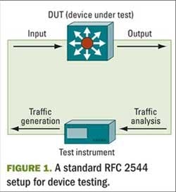
RFC 2544 [3] was published in 1999 by the Internet Engineering Task Force (IETF), an international community of network designers, operators, vendors, and researchers concerned with the evolution of the Internet architecture and serves as the main standards organization for the Internet. RFC 2533 [3] defines the “Benchmarking Methodology for Network Interconnect Devices” and was originally designed to allow the standardized testing and benchmarking of a single interconnect device such as a router or a switch, known as the device under test (DUT). This methodology has become the de facto test performed routinely in quality assurance and verification labs to quantify the performance of network devices. A classic test setup is illustrated in Fig. 1.
In this configuration, the test system injects traffic into the DUT, analyzes the frames coming out, and correlates the input and output to measure the transmission characteristics of the DUT. The RFC 2544 benchmarking methodology defines a series of performance measurements. Throughput, latency, frame loss, and back-to-back are the most common benchmark tests used in automated test suites.
Throughput measures the highest data rate at which no frames are dropped by the DUT. Frame sizes (in bytes) of 64, 128, 256, 512, 1,024, 1,280 and 1,518 should be used during the test. Once the throughput has been determined, a latency test measures the one-way delay through the DUT at the throughput rate. The frame loss test is used to determine the rate of frame loss across the entire range of input data rates and frame sizes. It is computed using the following formula:
Frame Loss = [(InputCount – OutputCount) × 100%]/InputCount
A back-to-back test measures the longest frame burst that the DUT can handle without any frame loss.
In addition to these tests, RFC 2544 defines the system recovery and the reset tests, which measure the speed at which a DUT recovers from an overload condition and a device reset. While providing important information, these tests are not typically used, as the metrics usually are not part of the carrier SLA and they are more difficult to include in an automated test suite.
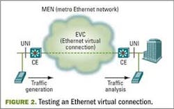
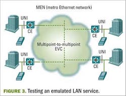
More recently, the RFC 2544 test suite has been adapted to measure the performance of systems and networks. Figure 2 illustrates this with an example of what MEF defines as the Ethernet Line (E-Line) service, which is essentially an emulation of a virtual circuit. Figure 3 shows an Ethernet LAN (E-LAN) service, which emulates a multipoint network.
Adapting RFC 2544 from testing a DUT in the lab to a production network in the field requires a few changes. Unlike a lab environment, the two measurement points in a network are geographically separated. This requires two or more test sets to measure the input and the output, one generating the traffic and the other receiving it. Field test units must be portable and deployed quickly in various locations. Finally, RFC 2544 and RFC 1242 define latency in terms of the one-way delay, yet in a network round-trip delays are measured as well.
Another common test scenario in field testing is the broadband access network with asymmetric bandwidth. In ADSL, for example, it is important to test the upstream and downstream separately. By inserting the test units at various points of the upstream network, field technicians can determine the throughput of the regional as well as access networks.
Triple-play service testing
For real-time applications such as voice and video, network transmission attributes such as packet delay, jitter, and packet loss can adversely affect the quality of the reception. For example, for IP telephony, the following are commonly recommended values to maintain acceptable voice quality:
- packet delay: less than 150 ms one-way (less than 100 ms one-way for toll-quality voice)
- jitter: less than 50 ms
- packet loss: less than 1%
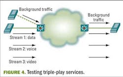
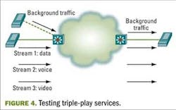
For triple play, technicians must be able to generate multiple data streams and verify that voice and video traffic are transmitted with the required performance. In these tests, the different streams can represent data, voice, and video.
How the network treats each stream depends on the network configuration. In some networks, all IP phones are assigned to a separate voice VLAN. In others, the IP phones are programmed to tag all traffic with higher priority using 802.1p. In designing a test, technicians must consider the network configuration infrastructure to effectively simulate the traffic mix. Figure 4 illustrates a typical setup.
Troubleshooting Ethernet
With Ethernet there are a number of common problems that can be identified quickly with the right test instruments. These problems may include:
- cabling error: the LAN cable is connected to the wrong port
- cable fault: there is a problem with the connector resulting in an open or short circuit
- speed or duplex mismatch: the network interface card is configured for a speed/duplex setting that is incompatible with that of the switch port
- DHCP error: stations are unable to obtain an IP address from the DHCP server
- duplicate IP address: multiple devices are configured statically with the same IP address
- routing problem: stations are unable to reach destinations outside the local VLAN either because the default gateway is down or configured improperly
To diagnose these problems quickly, field personnel need a number of different troubleshooting tools that today are included in lightweight, full-featured handheld test units. Common tools that are critical to have in a handheld test set include:
- a cable tester to check for any cable faults such as open and short circuits, and, using time-domain reflectometry, it can determine the length of the connected cable
- a port identifier that activates and deactivates the Ethernet port, causing the port LED on the switch to turn on and off periodically, allowing the technician to identify the switch port connected to a device
- a link status check that displays the link speed, duplex, and flow control when connected to a switch port
- a DHCP feature that allows the test unit to confirm that an IP address can be acquired successfully from the DHCP server
- a device scan for scanning a range of IP addresses looking for active devices
- PING, a standard function that probes an IP address using Internet Control Message Protocol and returns the round-trip delay between the test unit and the target device
- a standard trace-route function that traces the IP path to a target address identifying all the intermediate routers
Future requirements for Ethernet service OAM
Ethernet is a ubiquitous networking technology and carriers and service providers are under competitive pressure to provision such services quickly and cost-effectively. This pressure trickles down to field technicians who must verify the integrity of increasingly complex services in much less time. Although basic testing can verify connectivity, Ethernet service must be measured against SLAs as well, which requires the RFC 2544 test suite for measuring throughput, latency, frame loss, and back-to-back.
The growing use of Carrier Ethernet is driving the simultaneous rise in the need for Ethernet service operation, administration, and maintenance (OAM). The objective of this effort is to provide carriers with a comprehensive set of tools for monitoring the performance and availability of Ethernet services.
Already standards bodies are working to develop guidelines in this area. Some of the more advanced include the IEEE 802.3-2005 (previously 802.3ah) Ethernet Link OAM (Ethernet in the First Mile), IEEE 802.1ag Ethernet Service OAM, ITU-T Y.1731 OAM Functions and Mechanisms for Ethernet Based Networks, and the MEF 17 Service OAM Requirements and Framework.
As these standards mature, the prescribed tests—connectivity check, loopback, and link trace, for example—will need to be rapidly implemented in the field. To contain capital and operational expenditures, the best approach for service providers is to take advantage of modular test sets that can easily be upgraded in the field, without the need to invest in completely new systems.
Andy Hight is product marketing director at Sunrise Telecom (www.sunrisetelecom.com). He can be reached at [email protected].
One-CLICK LINKS
Lightwave:Ethernet OAM Test Applications
Lightwave: Carrier Ethernet Improves IP Service Delivery
Lightwave: Transport/Core Networks Require New Look at Test
