The increasing importance of extinction ratio in telecommunications
Defined and required by many standards, many variations of use between designers, manufacturers, and end users continue to plague the industry.
Bob Hasenick
Agilent Technologies, Inc.
This article describes how extinction ratio (ER) is defined and used within the telecommunications industry. A companion article in the October 2005 issue of Lightwave describes measurement and calibration methods for the characterization of extinction ratio.
Several physical-layer parameters are used to characterize optical signals, and most of these have specific limits and test conditions. Extinction ratio is an important measure of the quality of an optical signal, especially for modern transmitters. Extinction ratio is commonly misunderstood, can be harder to measure than other parameters, and is traded for performance with other parameters such as chirp1, fiber dispersion, and self-phase modulation. 2Designers, suppliers, and users of transceivers can benefit greatly from a common understanding of extinction ratio, where the careful choice of component parameters improves the interoperability of complex devices in short- and long-haul communications systems.
Use and significance of extinction ratio
Let's start with the impact of extinction ratio on system performance and other parameters. As the extinction ratio improves, the bit-error ratio (BER) improves, reducing the number of errors and the amount of error correction required. As higher data rates are being pushed through materials (such as FR-4 printed circuit boards), loss and dispersion close the eye and errors increase. This effect is commonly known as "power penalty," which has been thoroughly described in other sources. 3,4Briefly, poorer values of ER increase the power penalty (PP), worsen BER, and diminish the benefit of increased power. Equation 1 defines the power penalty as:
PP= -10log {(ER-1)/(ER+1)} (1)
where ER is defined as E1/E0. For example, a common ER value called out in a standard near 6 dB delivers a power penalty of 2 dB.
These factors become significant when the measured values from manufacturers differ from what designers measured, and the end user obtains different values than the manufacturer. The resulting discussions on yield and failures are rarely productive and can be remedied by the techniques in the October article.
ER provides a common metric for all users to characterize an optical signal. Minimum values of extinction ratio are called out in nearly all optical standards, including ITU-T G.691, G.957, and G.959.1. 5 Most standards reference EIA/TIA OFSTP-4A6 for the definition of ER and associated measurement conditions.All standards require the use of a filter when measuring ER, with the most commonly required filter being a fourth-order Bessel Thomson. A fourth-order Bessel filter closely approximates the integration of the signal to obtain an equivalent value of energy; the addition of Thomson specifies the filter be at three-quarters of the bit rate.
Definition of ER and associated challenges
To state a minimum or characteristic value for ER, we need to accurately determine the levels of "0" and "1." Three equations summarize how ER is expressed:
ER
ER% = 100 * (E0/E1) (3)
ER = E1/E0 (4)
where E1 = energy in a nominal logic 1 pulse E0 = energy in a nominal logic 0 pulse. 7Equations (1) and (2) are the dominant definitions, likely because dB and % are common measures for other parameters and are easier to compare than a ratio that can have very large numerical values. Note the use of the term energy rather than power, which is normally used. While power would seem the obvious choice, energy better characterizes the levels because the time interval is specified.
Industry standards vary in their definition of the portion of the bit period that is used. Standard ITU-T G.691 defines ER using values over the full width of the eye. Most other standards specify the use of histograms over the 40-60% of the bit period. The latter definition is easier to measure because of the significant amount of energy in the bit transitions.
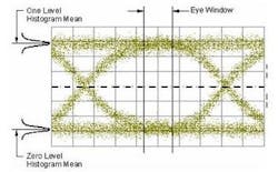
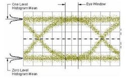
Let's now consider the means to establish the "0" and "1" levels. Figure 1 shows a typical eye diagram, which is used to obtain several parameters including ER.
Standard IEC 61280-2-2 calls for the use of histograms, which are regularly used to characterize the levels and give statistical parameters of the energy between the 40% and 60% area of the eye. 8 For low power levels or very poor extinction ratios, the histograms start to overlap, and at some point the ability to discern a "0" and "1" is very difficult and results in large errors. For the specified output powers of most modern transceivers, this is of less concern yet needs to be considered in the uncertainty calculations.Factors to consider when designing for ER
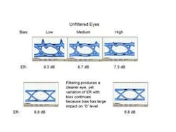
Designers and those who validate designs must consider several factors when designing transmitters, including choice of eye width, overshoot, slow edges (undershoot), and lack of a proper filter. Consider each of these while referring to Figure 2, which shows the effect on ER for different transmitter bias voltages.
Recalling that the levels for "0" and "1" are determined by the use of histograms, note that the histograms will have a much wider spread when evaluating the eye for ER over the entire bit period. This flatter histogram is affected by a wide range of bit transitions and more easily results in variations of the perceived values of "0" and "1," further contributing to differences between designers, manufacturers, and users.
Overshoot and lack of a proper filter similarly affect the histogram, whether measured over the center 20% or the entire bit period. No or poor filters leave the higher-frequency components of the signal in the eye, contributing to a higher value of "1" and lower value of "0" in the 40% region of the eye. Figure 2 shows that this increases the ER of the unfiltered signal and is attractive to a designer struggling to meet compliance specifications; the design will often violate another aspect of system design or not work well with other components.
The opposite effect occurs for slow edges or filters with too much rejection. The values for "0" and "1" are closer together than they would be for a cleaner eye, resulting in a poorer ER and more challenging system performance.
The Fibre Channel standard defines an alternative measure called "Optical Modulation Amplitude" (OMA). 9 While initially seeming to offer the same measure of quality, OMA depends on a standard test pattern similar to a square wave and differently reflects how a transmitter performs with a typical data pattern. Viewing this as a more stringent test of a transmitter can in turn penalize a designer using atypical operating conditions.Summary
Extinction ratio has become an important and common, albeit controversial, measure of transmitter quality. Defined and required by many standards, many variations of use between designers, manufacturers, and end users continue to plague the industry. These variations diminish or disappear when several design aspects of the transmitter are carefully considered in light (no pun intended!) of the principles outlined in this article. Refer to the follow-on article in the October 2005 issue of Lightwave for specific techniques regarding measurements and calibration.
References
1. Sung Kee Kim, O. Mizuhara, Y. K. Park, L. D. Tzeng, Y. S. Kim, and Jichai Jeong, "Theoretical and Experimental Study of 10 Gb/s Transmission Performance Using 1.55um LiNbO3-Based Transmitters with Adjustable Extinction Ratio and Chirp," IEEE Journal of Lightwave Technology, Vol. 17, No. 8, pp. 1320-1325, August 1999.2. Zhuang Li, Yongqi He, Bo Foged Jorgensen and Rune J. Pedersen, "Extinction Ratio Effect for High-Speed Optical Fiber Transmissions," International Conference on Communication Technology, Beijing, China, pp. S35-02-1 to 5, October, 1998.
3. Maxim Integrated Products, Application Note HFAN-2.2.0 entitled "Extinction Ratio and Power Penalty," Rev 0; May 2001.
4. Rijiv Ramaswam, and Kumar N. Sivarajan, Optical Networks: A Practical Perspective, Second Edition, Chapter 5, Morgan Kaufmann Publishers, 2002.
5. ITU Series G: Transmission Systems and Media, Digital Systems and Networks:
G.691 on Transmission media characteristics -- Characteristics of optical components and subsystems, December 2003.
G.957 on Digital transmission systems -- Digital sections and digital line system ¿ Digital line systems, July 1999.
G.959.1 on Digital sections and digital line system -- Digital line systems, December 2003.
6. TIA-EIA Document OFSTP-4A, "Optical Eye Pattern Measurement Procedure," TIA-526-4-A, November 1997.
7. "Measuring Extinction Ratio of Optical Transmitters," Agilent Technologies Application Note 1550-8, January 2001.
8. IEC Document 61280-2-2, "Fibre Optic Communication Subsystem Test Procedures, Part 2-2: Digital systems -- optical eye pattern, waveform, and extinction ratio measurement."
9. "Fibre Channel Physical Interfaces (FC-PI-2)," ANSI Working Draft, March 2005.
Bob Hasenick is product marketing engineer, digital signal analysis, at Agilent Technologies Inc. (Santa Rosa, CA).

