Optimized duobinary system designs save costs
As a simulator tool shows, the use of duobinary transmission can decrease the amount of dispersion-compensating fiber in network deployments.
Jigesh K. Patel
RSoft Design Group, Inc.
From classical electrical communication theory, it is well known that duobinary transmission effectively reduces intersymbol interference (ISI) penalties. Recent studies of similar transmission in the case of optical communication have suggested two distinct advantages: longer transmission distances without employing dispersion compensation and the potential to support more compact spectral channel plans for WDM systems.
In a previous article, we showed how a commercial simulation tool is crucial in optimizing costs by showing how to change the placement of dispersion compensating fiber (DCF) in a fiber-layout plan without affecting capital and operational expenditures.1 In this article, we show that using a professional simulation tool we can demonstrate how the higher spectral efficiency of duobinary transmission translates into lower dispersion penalties in optical communications without imposing any additional requirements -- either on the existing fiber plant or on the receiver. By the appropriate selection of the transmitter filter bandwidth, planners can save significant expenditures by reducing the number of necessary DCF spans.Effects of transmitter filter
To begin with, we first must understand the influence of transmitter band-limiting filters on the single-channel link performance. It is not necessary to employ any band-limiting filter at the transmitter. However, such a filter can restrict the spectral occupancy of the electrical modulating signal before driving the modulator, and we shall see that it can have an interesting impact on the overall system performance. Later, we will concentrate on the specific case of a transmitter filter that generates duobinary transmission.
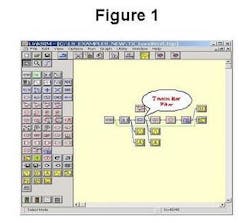
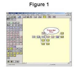
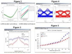
Figure 1 shows the topology of a 90-km, 1550-nm, single-channel optical link operating at OC-192 (10 Gbits/sec). The simulation was carried out using LinkSIM.2The filter employed to restrict the spectral contents of the electrical modulating signal in this example is a fifth-order low-pass Bessel filter. We define the filter's spectral efficiency as the ratio of input bit rate (bits/sec) to the filter's 3-dB bandwidth (in Hz). We run a parameter scan varying the spectral efficiency from 10% to 400%. The corresponding BER plot is shown in Figure 2a.
Figure 2b shows the BER along the length of the links having different transmitter filter pass-bands. The length of the fiber is varied between 80 and 95 km in uniform increments of half-a-kilometer each. It is interesting to see that the optimum performance does not occur when the filter is designed to have its 3-dB bandwidth closer to the input bit rate. Instead, optimal performance occurs when the cut-off frequency is approximately one-fourth of the bit rate. At this cut-off frequency, the spectral occupancy of the modulated optical field is restricted to [f0 ± (Bit rate)/2], where f0 is the nominal continuous wave (CW) laser frequency. As we shall see next, such a filter approximates a duobinary filter.3The receiver's electrical bandwidth requirement is identical for both the conventional non-return to zero (NRZ) and the amplitude-modulated phase-shift keyed (AM-PSK) duobinary system here. The frequency spectrum of an ideal duobinary signal exhibits the first nulls at [f0 ± (Bit rate)/2]. We can band-limit the signal at [f0 ± (Bit rate)/2] while preserving at the same time enough information for later reconstruction of the signal.4Duobinary data transmission
A duobinary data generator can be implemented by using either (A) a dual-drive Mach-Zehnder (MZ) modulator or (B) an equivalent electrical filter to drive a single-arm MZ modulator. The duo-binary stream can then be passed through an optional band-limiting filter with a cut-off frequency equal to half the bit rate. This optional filter is shown to limit the linear crosstalk in DWDM systems.5 Alternatively, the implementation of (B) above with filter cut-off at one-fourth of the bit rate can equivalently model the duobinary stream of (A) and the following band limiting filter. In this article, we model a duobinary data generation scheme as implementation (B).Figure 3 shows base-band spectra plots for binary NRZ and duobinary NRZ transmissions. The duobinary filter compresses the spectral occupancy of the signal, thereby helping to create a tighter spectral packaging of multiple channels in WDM systems.
Figure 4 shows single scan eye diagrams for conventional binary NRZ (left) and duobinary filtered NRZ data (right) transmitted through a 90-km standard singlemode fiber (SMF) with 17-psec/nm.km dispersion.
We now run a parameter scan twice (once for the binary NRZ case and the other for the duobinary NRZ case) with dispersion of the SMF varying from 3 psec/nm.km to 20 psec/nm.km. Most of the off-the-shelf standard SMF and dispersion-shifted SMF fall within this range of chromatic dispersion. Figure 5 shows BER plots for these simulations.
When the dispersion is low, NRZ binary and duobinary formats perform equally well. However, as the dispersion goes on increasing further, the NRZ duobinary scheme clearly outperforms the conventional binary NRZ modulation.6-8 It is interesting to note that the duobinary scheme does not impose any extra restrictions on the receiving filters, and can use the same receivers as currently used by the conventional NRZ systems.Acknowledgements: The author wishes to thank his colleagues Dr. Brent Whitlock, Dr. Mike Steel, Dr. Rob Scarmozzino, Dara Mirsky, LuAnn Scarmozzino, Dr. Feng Ma, Dr. Gary Shaulov, Dr. Jim Morikuni, and Dr. Pablo Mena for their timely inputs and stimulating discussions.
References
1. Patel, J., "Dispersion-management modeling resolves system-design issues," WDM Solutions, March 2002, pp. 43-48.
2. http://www.rsoftdesign.com/products/system_simulation/LinkSIM/
3. Walkin, S., and Conradi, J., "On the relationship between chromatic dispersion and transmitter filter response in duobinary optical communication systems," IEEE Photonic Technology Letters, vol. 9, no. 7, July 1997, pp. 1005-1007.
4. Lee, E.A., and Messerschmitt, D.G., Digital Communication, 2/e, Kluwer Academic Publishers, Norwell, MA, USA, 1994.
5. Shtaif, M., and Gnauck, A.H., "The relationship between optical duobinary modulation and spectral efficiency in EDM systems," IEEE Photonic Technology Letters, vol. 11, no. 6, June 1999, pp. 712-714.
6. Loh, W.H., Laming, R.I., Ellis, A.D., and Atkinson, D., "10Gb/s transmission over 700 km of standard single-mode fiber with 10-cm chirped fiber grating compensator and duobinary transmitter," IEEE Photonic Technology Letters, vol. 8, no. 8, September 1996, pp. 1258-1260.
7. Yonenaga, K., and Kuwano, S., "Dispersion-tolerant optical transmission system with duobinary transmitter and binary receiver," Journal of Lightwave Technology, vol. 15, no. 8, August 1997, pp. 1530-1537.
8. Gu, X., Dodds, S. J., Blank, L. C., Spirit, D. M., Pycock, S. J., and Ellis, A. D., "Duobinary technique for dispersion reduction in high capacity optical systems ¿ modelling, experiment and field trial," IEE Proc.- Optoelectronics, vol.143, no. 4, August 1996, pp. 228-236.
Jigesh K. Patel ([email protected]) is currently with RSoft Design Group, Inc. (Ossining, NY). The author can be reached at RSoft Design Group, Inc., 200 Executive Boulevard, Ossining, NY 10562 (Phone: 914-923-2164).


