Moving to 40-Gbit/sec components
Higher-speed and higher-capacity transmission systems require novel optoelectronic devices.
HAVA VOLTERRA, CyOptics
With the rapid evolution of optical-networking technology, carrier expenditures this year for 10-Gbit/sec optical transmission are projected to surpass expenditures for 2.5-Gbit/sec systems. In addition to rapid increases in speed at the core of the network, transmission speeds at access and metropolitan distances are increasing as well. This trend has brought a surge in demand for short- and intermediate-reach 10-Gbit/sec optical interfaces.
As speeds increase at both the core and periphery of the network, carriers and equipment vendors are looking to 40-Gbit/sec transmission systems to provide an extra boost in speed and fiber-carrying capacity. Demand is being generated for solutions to both short- and long-reach transmission.The technological challenges of transmission at 40 Gbits/sec are formidable, however, and solutions are required in several areas. In particular, ultra-high-speed optical transmission components, new amplification systems, enhanced dispersion compensation, highly sensitive receivers, and corresponding electronic components are required.
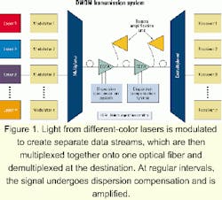
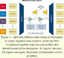
Figure 1 shows a basic DWDM transmission system. Multiple laser sources at different colors are modulated by data signals, then multiplexed together onto one fiber. Depending on transmission distance, there may be one or many amplification stations along the way. At the receive side, the light channels are demultiplexed and each channel is serviced by a dedicated receiver.
In reviewing the diagram, it becomes apparent that only two of the components in the transmission system need to actually operate at 40 Gbits/sec-the modulators and the receivers. These components are the core of the transmission system, both in single- and multiple-channel systems. Development work in high-speed transmission is specifically focused on these devices.In addition, several of the components need to be specially tuned to 40-Gbit/sec systems. The primary components are the dispersion compensation systems and the amplification units. Dispersion compensation systems are important for longer-distance 10-Gbit/sec transmission. But at 40 Gbits/sec, the dispersion challenges are significantly higher and different types of dispersion become significant. As a result, dispersion compensation becomes essential even for intermediate distance 40-Gbit/sec transmission, and planning for it becomes essential in the system design.
Along with dispersion compensation, higher levels of amplification are needed as well as new approaches to amplification. New Raman amplifiers are expected to be essential in any long-haul 40-Gbit/sec transmission system since they enable higher levels of amplification without the penalty of excessively high power peaks near the amplification units.
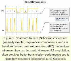
Most optical transmission systems operating at 2.5 and 10 Gbits/sec use a standard transmission format called nonreturn-to-zero (NRZ) transmission (see Figure 2). In NRZ transmission, a "1" is denoted by light on, and a "0" is denoted by light off. This format is called non-return-to-zero because a series of "1"s will keep the light on through multiple data bits.
At 40 Gbits/sec, transmission through optical fiber becomes significantly more challenging. Several effects that have negligible impact at lower speeds become very significant and can prevent effective data transmission. In particular, nonlinear effects in fiber are manifested and caused by the signal itself. Among these effects are self-phase modulation, cross-phase modulation, and four-wave mixing.
To counteract these nonlinear effects, different data modulation techniques have been tested. Most of these new modulation techniques are variants of a different type of transmission format, called return-to-zero (RZ) transmission (see Figure 2). In RZ transmission, a "1" is denoted by a pulse and a "0" by the lack of a pulse. Thus, a series of "1"s (pulses) will have a return to zero between each bit of information.The reasons that RZ counteracts fiber nonlinear effects are not fully understood, but many mechanisms are speculated. One reason is that the time period in which light is on is shorter, leading to less interaction between channels and therefore less four-wave mixing and cross-phase modulation. Another reason is that in RZ modulation, the nonlinear effects counteract some of the linear fiber distortions that are well known at lower speeds, such as chromatic dispersion. That is the case with soliton transmission, which is a special case of RZ transmission.
In soliton transmission, the power of the pulse is matched to the fiber to achieve a pulse that maintains itself almost indefinitely through fiber. While in real-world applications, variations in the type and quality of fiber may yield less-than-ideal soliton transmission, various methods have been developed to counteract these problems and achieve excellent transmission results.
As the devices that determine the ultimate quality of the transmitted signal, 40-Gbit/sec modulators need to adhere to very high performance standards in many parameters (see sidebar, "Specifications for 40-Gbit/sec active components"). First, they need to provide the requisite bandwidth required to generate a 40-Gbit/sec signal. They must provide this signal using low drive voltage and with very low chirp.Traditionally, optical data modulators have been made of lithium niobate (LiNb3) material using a Mach-Zehnder interferometer. While the performance of these devices is good, their use becomes more difficult with higher frequency. LiNb3 modulators become significantly larger with frequency, and their drive voltage requirements increase. In addition, they do not lend themselves well to high-volume manufacturing.
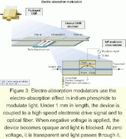
Another modulator, made of indium phosphide (InP) semiconductor and utilizing the electro-absorption effect in InP materials, is emerging as a highly effective alternative for 40-Gbit/sec transmission. The InP electro-absorption modulator (EAM) is much smaller than a LiNb3 modulator (in fact, the internal chip size is less than one-hundredth the size of a LiNb3 modulator chip), and its drive voltage is significantly lower.
An EAM chip consists of three sections: one active section with two passive sections on each side (see Figure 3). The passive sections contain only passive waveguides, used for mode shape management and coupling light in and out of the fibers. The active section contains both a passive waveguide and an active layer. Light is coupled into the active layer from the passive waveguide. Modulation is achieved by applying varying reverse bias on the chip, generating a varying electric field in the appropriate direction across the active layer.
Since the EAM is a semiconductor device, it lends itself to economies of scale in manufacturing similar to those found in the semiconductor industry. A wafer of InP 2 inches in diameter can yield several thousand high-performance devices. More complex devices, including two or more EAMs along with passive waveguides, can be manufactured as well.
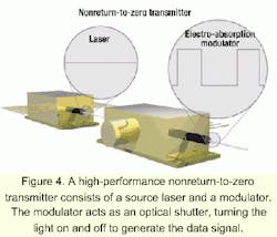
The EAM has the additional advantage of integrating with other devices to create highly compact, multifunctional devices. For example, a laser or tunable laser can be integrated with an EAM to create a very compact, high-performance NRZ transmitter (see Figure 4). Two EAMs, along with a laser, can be integrated to create a very high-performance RZ transmitter.
The 40-Gbit/sec receiver is complementary to the 40-Gbits/sec data modulator. Receivers consist of an optical detector with an integrated electronic preamplifier such as a transimpedance amplifier. A primary requirement of the receiver is high bandwidth-to match the transmission bandwidth. An additional requirement is high sensitivity and low noise levels, enabling the receiver to properly identify the bits of a data stream.
At data rates up to 10 Gbits/sec, most optical detectors are either surface-illuminated positive intrinsic negative (PIN) photodiodes or avalanche photodetectors (APDs). APDs have significantly higher sensitivity than PINs and are therefore favored for long-haul applications. PIN receivers are usually used for short reach.
A PIN detector consists of three main layers-positive, intrinsic, and negative-and under reverse bias, an incident photon generates an electron-hole pair that is pulled from the depletion layer by an electric field to generate a photocurrent. An APD structure is similar to that of a PIN, except that its active region consists of an additional avalanche layer. This avalanche layer can generate multiple electron hole pairs from a single photon, thus providing higher current response (or higher sensitivity) than a PIN device.
At 40 Gbits/sec, the bandwidth requirement quadruples, while most of the other key parameters need to remain constant. However, surface-emitting photodetectors have an inherent tradeoff between bandwidth and responsivity, and APDs cannot operate at such high bandwidths. To address these limitations, many of the new 40-Gbit/sec detectors are waveguide PIN detectors, which are similar in structure to EAMs and can operate at a higher frequency (bandwidth) while providing high sensitivity.
Today, 40-Gbit/sec electronics are above the realm of mainstream digital design and require special skills that have traditionally been honed in the microwave and radar arenas.
In addition, traditional complementary metal-oxide semiconductor (CMOS) technologies do not lend themselves to serial 40-Gbit/sec electronics. For that reason, different materials are being evaluated for 40-Gbit/sec electronics, including silicon germanium (SiGe) and gallium arsenide (GaAs). In addition, InP, the same material being used for EAMs and receivers, is being used.
Hava Volterra is vice president of marketing and business development at CyOptics (Waltham, MA). She can be reached at [email protected].
- 3-dB modulation bandwidth. This parameter is used to evaluate the bandwidth of a modulator. It indicates the frequency at which the output of the modulator falls to one-half its value at low frequency. The parameter is a good indication of the frequency response of the modulator and an indicator of the quality of the light signal it can generate at high bit rates.
- Chirp. The opening and closing of a modulator can cause slight variations in the frequency of the light passing through it, known as chirp. Modulator chirp is often adjustable. Depending on its characteristics and the characteristics of the transmission system, the chirp can be either a help or a hindrance to transmission.
- Insertion loss. Modulator insertion loss is the ratio between the input power and the output power of the light passing through the device.
- Contrast ratio. This ratio is measured on return-to-zero (RZ) signals as the ratio between the peak power of a pulse and the minimum power between pulses. Higher contrast ratios are desirable, since they lead to higher accuracy on reception.
- Extinction ratio. Modulator extinction ratio is the ratio between light output from the modulator in its "on" (open) state and its "off" (closed) state. Higher extinction ratios are generally desirable for longer-haul transmission.
- FWHM. Full width at half maximum (FWHM) is the parameter most widely used to express the width of an RZ pulse. Along with pulse shape, this parameter is essential in characterizing the pulse.
- Modulation voltage. This parameter is the peak-to-peak voltage required to open and close the modulators. The extinction ratio is defined as a function of the modulation voltage that is used.
- Polarization sensitivity. Modulators may have different transmission characteristics, depending on the polarization state of the incident light. This dependency is referred to as polarization sensitivity, or polarization-dependent loss.
- 3-dB bandwidth. On detectors and receivers, 3-dB bandwidth is the bandwidth at which the output voltage, or current swing, is half the level of the swing at low bandwidth. This parameter is an indicator of the frequency response of the receiver and the speed of the signal it can properly detect.
- Sensitivity. In detectors, sensitivity is defined as the minimum optical input power detected by a receiver at a certain bit-error rate and is expressed in decibel related to milliwatt (dBm).
- Responsivity. In detectors, responsivity refers to the ratio of photocurrent generated by the detector per watt of optical input power. It is expressed in amperes per watt (A/W).
