IC toolkit for optical-link improvement
The recent emergence of electronic dispersion compensation (EDC) for singlemode and multimode fiber has generated a lot of excitement in the communications industry and is arguably one of the more fashionable coffee-room topics among system providers today. The buzz on this topic is deserved—EDC provides a compelling way to improve overall link budget versus more costly optical alternatives.
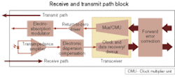
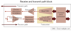
However, EDC is not a cure for all transmission woes. In fact, when it comes to interoperability with legacy systems, EDC offers its share of challenges. It is just another tool in an ever-expanding kit of IC technologies that when used in combination gives the system designer the ability to compensate for fiber impairments to an extent not previously possible.Other technologies in this IC toolkit include transimpedance amplifiers (TIAs) with threshold-level adjustment, serializer/deserializer (SerDes) devices with adaptive (or "smart") receivers, transport processors equipped with standards-based or proprietary forward error correction (FEC) algorithms, and return-to-zero (RZ) laser drivers coupled with electro-absorption (EA) modulators (see Figure 1).
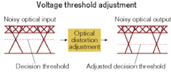
We start first on the receive path with the TIA, which converts the current produced by a photodetector into a voltage signal. Optical communications systems have several types of impairments that can degrade system performance, including dispersion due to long spans of fiber and noise introduced by optical nonlinearities and amplified spontaneous emission in an optically amplified system. In ordinary TIAs, the resulting low optical-signal-to-noise ratio (OSNR) produced from these effects would undoubtedly translate into a reduction in overall optical sensitivity.Moving the threshold voltage to the effective center of the distorted data eye to account for optical impairments provides a measurable improvement in performance. In a 10-Gbit/sec optical system with a 21-dB OSNR, optimizing the threshold level reduced the BER from 10–3 to 10–10 (see Figure 3). The same TIA provided an average improvement of 0.5 dB in the minimum amount of OSNR needed to achieve a BER of 10–10 over a 50-km span (10-Gbit/sec nonreturn-to-zero [NRZ] signal with 231–1 PRBS pattern).
Next in the receive path is the EDC chip. EDC is actually a broad term that, depending on the chip supplier, might imply one of several fiber impairment compensation techniques. For our purposes, an EDC chip uses classic tapped delay line finite impulse response (FIR) filtering techniques (such as feed-forward equalizer and decision feedback equalizer) to compensate for chromatic dispersion or modal delay, maximizing the Q-factor at the center of the data eye.
A key application for this technology is the successful transmission of serial 10-Gbit/sec 1310-nm signals over 300 m of multimode fiber, but the same concepts are proving effective for longer spans across singlemode-fiber applications as well. Multimode fiber exhibits modal delay in which multiple copies of the transmitted pulse train arrive at the receiver at different times. Singlemode fiber exhibits chromatic dispersion, in which the spreading of each pulse occurs as the pulse train travels down the fiber. Both impairments result in potentially large amounts of intersymbol interference (ISI). Depending on the number of taps and filter coefficients applied, EDC can reduce the ISI substantially for a given channel response and distance objective.
Simulation results show that optical performance benefits of up to 3 dB in dispersion penalty compensation can be expected when using EDC. As this technology is incorporated into a growing number of new 10-Gbit/sec applications, the practical performance benefits are becoming clearer. For size- and power-sensitive optical-module applications, the challenge for chip suppliers is to provide this function with minimal increase in power, price, or package footprint over existing SerDes and CDR chipsets without EDC.
Suppliers are beginning to offer EDC technology coupled with CDR and/or demultiplexer functions in a single chip. When implemented in CMOS, the power dissipation required for the addition of this function is on the order of a couple of hundred milliwatts.
It is important to note that interoperability with legacy systems is a concern and may limit the adoption of EDC in existing applications. For example, if one end of a bidirectional fiber link has EDC and the other corresponding receiver does not, the overall link budget constraints will still be limited by the weaker receiver. While it remains to be seen whether the industry can overcome the challenges associated with deployed systems, it is clear that this technology will find more general acceptance in the newer applications described above.
Transceiver ICs—10-Gbit/sec CMOS multiplexer/CMU (clock-multiplier-unit) CDR/demultiplexer SerDes chips—are now offering system designers a low-power, monolithic approach for interfacing receive and transmit path traffic to higher-layer chip functions such as FEC and framing/mapping. Advantages include not only minimal footprint, but also the ability to perform diagnostic loopback functions otherwise not possible with separate multiplexer and demultiplexer chips.
"Smart-receiver" technology is now available for the CDR/demultiplexer function at the cost of an additional 300 mW. With this added feature, it is now possible to monitor the shape of the received data eye using an external microcontroller and make decisions regarding CDR sampling point phase and voltage adjustment, with no impact on the SerDes IC footprint.
The eye can be monitored and the sample point adjusted in real time in a two-dimensional adaptive optimization algorithm, without interruption to the transmission of data. That allows optical modules and line cards to automatically find the optimal eye sample point without external FEC feedback, automatically respond to changing optical conditions, enable multivendor module interoperation, and perform optical performance monitoring. Benefits include the ability to measure real time data eye Q-factor, integrated DACs to drive TIAs equipped with threshold adjust, and better performance over very long spans in the presence of polarization-mode dispersion (PMD) and low OSNR.
A recent study showed that 2D-adaptive sampling and equalization in the receiver decision circuit provides significant power penalty reduction over a conventional receiver. It demonstrated that the 2D-adaptive smart receiver was able to reduce the power penalty from 5 dB to about 2 dB for a 1,000-km long-haul (LH) span in a 10-Gbit/sec NRZ transmission system.1
Following the demultiplexer function, FEC ICs ("transport processors") can provide significant improvement in BER. They achieve that by encoding data in the transmit direction with appended check symbols (or overhead) and using this redundant check symbol data to decode and correct bits in the receive direction. They also provide the specific number of corrected 1s versus 0s, which can be used to better direct the efforts of TIAs with threshold adjust and smart receivers. There are two main types of FEC codes:
- "Standards-based" codes operate using published algorithms and overhead, thereby enabling the system designer to mix and match vendors on transmit and receive nodes. ITU-T G.975 is the foremost standard in optical networking, providing an interoperable code to achieve 6-dB net electrical coding gain with 7% overhead. Standards-based codes are typically used for metro-based systems.
- "Proprietary" codes are vendor-specific and typically provide much higher gain, although often at the cost of higher overhead (up to 25%). These codes are a good choice for point-to-point links or LH/ultra-long-haul (ULH) applications. However, proprietary codes with 7% overhead are available that can achieve about 9-dB OSNR gain. Since the amount of overhead directly translates into a higher bit rate and therefore dictates the need for more expensive optics and electronics, the 7% codes have more mainstream appeal.
Performance results show that a 7% enhanced FEC device at 10 Gbits/sec enables a Mach-Zehnder modulator biased for zero-chirp to achieve dispersion-limited performance up to about 115 km and a dispersion penalty of under –3.6 dB at 80 km. Without FEC enabled, the same transmitter exhibits a BER floor at 100 km and has a 2.8-dB dispersion penalty at 80 km. Likewise, when using an 80-km externally modulated laser and PIN receiver with FEC enabled, this device has been shown to extend reach to over 135 km.2
There are several IC driver technologies available that boost signal propagation through the transmit path over and above that of typical NRZ signaling. These technologies include duobinary encoders, which offer resilience to dispersion via a three-level signaling approach, and return-to-zero (RZ) signaling, which represents a "1" bit with a narrow high-energy pulse. Focus here is given to RZ signaling, which has enjoyed some recent advances.
RZ transmission is a good choice for LH or ULH applications but requires a higher-bandwidth driver and expensive optical components. Traditionally, an RZ transmitter design includes a continuous-wave laser, two lithium niobate modulators, and high-voltage data and clock drivers that require a large amount of electrical power. This approach is costly and complex to implement.
A more efficient approach has been demonstrated that incorporates the use of an RZ laser driver and EA modulator. This combination uses 30% less power, reduces costs by 70%, and results in an 80% reduction in overall footprint. ULH links of >6,000 km have been demonstrated using this approach. While NRZ is entrenched in the industry as the transmission mode of choice, transmitter advances such as this will likely continue to help alternative signaling approaches that were previously thought too expensive or esoteric to gain more acceptance.
A complete IC toolkit exists with receive and transmit path solutions for overcoming the losses associated with optical fiber. On the receive path, TIAs with threshold adjustment compensate for nonlinear noise, EDC chips use FIR filter techniques to reduce ISI, and smart receivers provide a means for mapping the shape of the received data eye to make intelligent decisions about where to adjust the CDR sampling point in phase and voltage.
On the transmit path, transport processors encode a signal using either a standards-based or proprietary code and can correct bits in error. RZ laser drivers work together with EA modulators to offer an efficient and less expensive way to improve link transmission. Other transmitter drive techniques are also available.
Several IC technologies should be considered when designing a system for optimal performance in the wake of dispersion effects typical in optical fiber. When taken in combination, these components offer the system designer a flexible and powerful set of electronic tools in the effort to maximize bandwidth at lower cost.
Richard Interrante is applications engineering manager, Vitesse Transport Division, at Vitesse Semiconductor (Camarillo, CA). The author extends many thanks to Badri Gomatam, Matt Dru, Matt Bolig, Lee Walter, Gary Paules, and Tony Conoscenti for their consultation and Lian Zhao and Frank Chang for generating the data presented here.
- "Reach Extension in 10-Gb/s Long-Haul Fiber Links with Adaptive Eye Mapping in a Si-CMOS 16-bit Transceiver IC," L.S. Yan, Y. Chang, S. Killmeyer, B. Gomatam, R. Talaga, T. Luo, A.E. Willner, University of Southern California.
- "Combating Dispersion in the OTN: Vitesse FEC Platform Enables Electroabsorption Modulators to Span 120 km (2400 psec/.nm)," B. Gomatam, Y. Chang, W. Li, K. Gandhi, A. Srivastava, Vitesse Semiconductor.


