PMD: Playing Russian roulette with your network
A network link must be designed to accommodate a certain value of polarization-mode dispersion and ensure that the probability of network outages is less than a few minutes per year.
DR. ALAN WILLNER, Phaethon Communications and the University of Southern California
Consider one of the strangest occurrences in the history of lightwave communications. We know today that something called polarization-mode dispersion (PMD) is a key limiter in the deployment of <10-Gbit/sec optical systems. To the first order, PMD is due to an asymmetry of the fiber core, in which light polarized in one axis travels faster than light polarized in the orthogonal axis.1,2,3 Yet, for all the millions of fiber-kilometers deployed prior to the mid-1990s, no parameter on the spec sheet ever mentioned a PMD value during the sale of that fiber.
Given that systems in the 1980s were barely reaching 1-Gbit/sec speeds, there was no reason to assume that PMD was an issue. In fact, the only way the major carriers could determine the PMD value post facto of their installed fiber plant was to open up some randomly selected segments of deployed fiber and measure it. They found fiber that had a range of nearly three orders of magnitude in PMD values. The world is covered with fiber whose PMD value is unknown.Thankfully, today's fiber has a very low PMD value and is well characterized. But there is still a small residual asymmetry in the fiber core. Moreover, slight polarization dependencies (i.e., PMD and polarization-dependent loss) exist in discrete inline components such as isolators, couplers, filters, erbium-doped fiber (EDF), modulators, and multiplexers. Therefore, even under the best of conditions, PMD will still significantly limit the deployment of 40-Gbit/sec systems.
What's the connection between PMD and Russian roulette? PMD is a random and time-varying process because:
- Each short discrete length of fiber will have a slightly different core asymmetry.
- The extent of the signal degradation caused by PMD is dependent on the state of polarization of light at a given point in the fiber link.
- The state of polarization of an optical signal will wander randomly due to temperature changes and mechanical stress.
There is literally no way to know the effect of PMD a priori. In fact, a system can be built on day one, operate flawlessly for 364 days, then go down on the 365th day due to PMD. Unless a link is designed to accommodate a certain value of PMD and ensure that the probability of a large power penalties (i.e., network outages) is less than a few minutes per year, the system planners are playing Russian roulette with their optical network.
Light is a wave, and it oscillates as it propagates along a fiber. The wave can oscillate up and down or side to side, representing either vertical or horizontal states of polarized light, respectively. Light is usually some combination of the two polarization states, and the combination of the states wanders as the light propagates inside the fiber.
The core of an optical fiber is not perfectly circular, and the resultant ellipse has two orthogonal axes. The index of refraction of a waveguide, which determines the speed of light, depends on the shape of the waveguide as well as the glass material itself. Therefore, light polarized along one fiber axis travels at a different speed, as does light polarized along the orthogonal fiber axis.
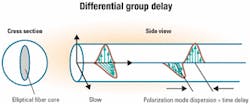
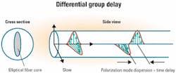
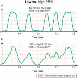
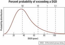
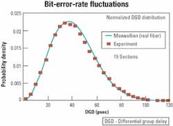
When the core of the fiber is bathed with light from a single "1" bit, then some of the light can be considered as polarized along one axis and some of the light polarized along the orthogonal axis. The differential light speed will cause a temporal spreading of the bit into two "modes" and will limit the ultimate system performance (see Figure 1). To the first order, that is a differential group delay (DGD). But each of these two modes will be further split when encountering the next fiber segment, ultimately generating even higher-order polarization-dependent dispersion effects.Perhaps the most important issue to remember is that PMD is random and follows a Maxwellian probability density function (see Figure 3). At one extreme, a Maxwellian distribution has a probability of occurrence for very small DGD values, meaning there is some small probability that all the short segments of fiber will align in such a way so as to internally cancel all the DGD of the entire fiber span. At the other extreme, a Maxwellian distribution always has some finite probability of occurrence for values of DGD that extend out to infinity.
Every link that has some PMD also will have some nonzero probability that the light will hit the fiber axes in exactly the worst way possible at every point along the entire fiber span, and then that link will go down. The only issue is when: Will it be once a day, once a year, or once every 10 years? This is the ugly head of PMD! It is therefore important to know the average PMD value for a link, since that determines the extent of the deleterious distribution tail of the Maxwellian distribution.
Another distasteful aspect of PMD is that the effects are different and uncorrelated for each independent channel in a WDM system.4 Therefore, PMD compensation modules would seem to require a separate PMD compensator for each channel in a WDM system.
Back in the early '90s, Craig Poole of AT&T Bell Laboratories was one of the first researchers to identify PMD as a critical challenge, and his seminal work is still the basis for much of today's understanding of PMD.5 The most powerful demonstration of the random affects of PMD might be the measurement of the bit-error rate (BER) during transmission of a signal through a fiber link in which the temperature changed by only a few degrees. For one experiment, Poole placed a spool of fiber outside the building and measured the BER fluctuations due to the random nature of PMD under environmental changes. As shown in Figure 4, a change of even one degree can change the BER by a factor of 50.6It is fairly instructive to consider a real link when evaluating the limitations placed on an optical system. The first issue to consider is the fiber itself. Today's fiber PMD coefficient is 0.1-0.5 psec/(km0.5). Older fiber may have values between 1 and 100 psec/(km0.5), while unofficial announcements of next-generation fiber boast a value of 0.05 psec/(km0.5). Secondly, there will be many inline components in a link that induce additional PMD, chief of which are erbium-doped fiber amplifiers (EDFAs) that are placed roughly every 80 km apart. We can safely assume PMD values for an EDFA module to be 0.2-1 psec.
Finally, many of the high-performance 40-Gbit/sec systems will incorporate forward error correction (FEC) coding.7,8 Such coding adds some redundancy into the bits of a data stream to more easily find and correct errors. FEC is implemented using electronic chips, and it adds a system power margin that can ease the deleterious problems associated with fiber non-linearities, chromatic dispersion, signal-to-noise ratio, and, of course, PMD.
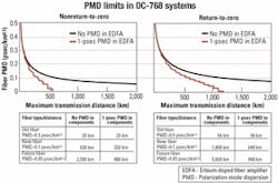
Although 10-Gbit/sec systems can be designed to minimize the problems of PMD by using newer low-PMD fiber, that's not the case with 40-Gbit/sec systems. Figure 5 combines all the issues mentioned and shows the approximate distance limitations for a 40-Gbit/sec system. Two types of signal formats are considered in Figure 5: nonreturn-to-zero, in which the optical power stays high throughout the entire time slot of a "1" bit, and return-to-zero (RZ), in which the optical power stays high in only part of the time slot of a "1" bit. Note that a strong FEC scheme is assumed whose benefits in system power margin are dedicated completely to mitigate PMD, which would not be the case in a real network.
Even under the best of circumstances, PMD will limit system performance. Moreover, the best-case scenarios quickly fade when the following real-life issues are considered:
- It is quite unlikely that a 1,000-km link will be homogeneously composed of only the best kind of fiber but would probably include some non-state-of-the-art fiber.
- Long-distance fiber links will inevitably undergo repairs and modifications that will alter the carefully balanced PMD equation.
- Reconfigurable optical networking, including add/drop multiplexers and crossconnects, will change the path of the signal, thereby necessitating that all possible routes be extremely well engineered to overcome PMD.
Systems designers actually have another unique problem in solving PMD. Since PMD is a random process, it is very difficult to build a laboratory experiment or field trial that accurately represents all possible PMD scenarios. One method is to use a PMD emulator composed of several spliced short sections of polarization maintaining fiber, in which the orientation of each splice is randomly and fully rotated to accurately emulate the entire Maxwellian distribution within a very short time.10 Waiting for a year to see if something goes wrong is certainly not a practical approach.
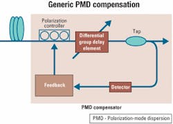
It would be quite advantageous to implement a module that would compensate for PMD effects in a fiber link. The generic diagram of a PMD compensator is shown in Figure 6. A polarization controller is used at the input to rotate the incoming signal polarization and optimally align it to a DGD element that will correct for some amount of the accumulated PMD. After the DGD element, a feedback loop is necessary to tune the polarization controller and thereby dynamically track changes in the state of polarization of the incoming signal. The feedback loop consists of a PMD monitor and should enable tracking within a few milliseconds. There are several methods for monitoring the PMD, including measuring the signal eye opening, the BER, the amount of radio frequency, and the degree of polarization.
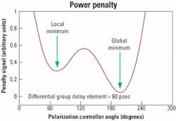
Perhaps the most difficult part of a PMD compensator is the tracking software required in the feedback loop. Such software requires a complicated control algorithm for finding the optimal position to minimize the system power penalty caused by PMD. The space explored by the control software consists of many pockets of local PMD minima, whereas there is only one true global minimum.Moreover, even if the compensator is locked onto a global minimum, the multidimensional system search space can easily change so that a new global minimum will appear. The old global minimum slowly degrades and becomes a local minimum, and the compensator is "stuck" at a new non-optimal local minimum. Figure 7 shows the case for rotating the polarization controller based on the feedback loop in which a local and global minimum appear.
The DGD element in the compensator can be:
- A single piece of polarization-maintaining (PM), highly birefringent fiber that produces a fixed amount of time delay.
- A tunable element that produces a varying amount of time delay and requires an additional feedback control signal.
- Multiple sections of PM fiber, in which each section would require its own feedback-controlled polarization rotator element.
The industry stands at a crossroad whereby strategic decisions will be made in the coming year by many network operators on the extent of deploying 40-Gbit/sec systems. There are several technical stumbling blocks to 40-Gbit/sec deployment, including the availability of critical components. These components include optical modulators; electronic drivers; low-noise lumped, and distributed optical amplifiers; tunable chromatic dispersion compensators; PMD compensators; and optoelectronic receivers.
Since there are significant remaining challenges in each category, none of these components is currently commercially available in bulk quantities. In particular, whereas all the other components mentioned here have already been deployed in their lower-speed versions for 10-Gbit/sec systems, PMD compensators have the added handicap of not being deployed at all for 10-Gbit/sec systems.
Clearly stated, other than prototypes and field trials, there are no PMD compensators currently deployed in any commercial system. PMD compensators remain the one true unknown for the future 40-Gbit/sec systems. The deployment of PMD compensators thus can be considered a key gatekeeper to the eventual deployment of robust high-performance 40-Gbit/sec systems.
Dr. Alan Willner is founder and chief technical officer at Phaethon Communications (Fremont, CA), and he can be reached via the company's Website, www.phaethoncommunications.com. He also is an electrical engineering professor at the University of Southern California/Los Angeles, is the editor-in-chief of the IEEE/OSA Journal of Lightwave Technology, and received the NSF Presidential Faculty Fellows Award from the White House.
- C.D. Poole and R.E. Wagner, "Phenomenological approach to polarization dispersion in long singlemode fibers," Electronics Letter, Vol. 22, pp. 1029-1030, 1986.
- N. Gisin, R. Passy, J.C. Bishoff, and B. Perny, "Experimental investigations of the statistical properties of polarization-mode dispersion in singlemode fibers," IEEE Photonics Technology Letters, Vol. 5, pp. 819-821, 1993.
- J.P. Gordon and H. Kogelnik, "PMD fundamentals: Polarization-mode dispersion in optical fibers," Proceedings of the National Academy of Sciences, Vol. 97, No. 9, April 2000.
- M. Karlsson and J. Bretel, "Autocorrelation function of the polarization-mode dispersion vector," Optics Letters, Vol. 24, pp. 939-941, 1999.
- C.D. Poole and J. Nagel, "Polarization effects in lightwave systems," Optical Fiber Telecommunications, Vol. IIIA, pp. 114-161, I.P. Kaminow and T.L. Koch, eds., Academic Press, 1997.
- C.D. Poole, R.W. Tkach, A.R. Chraplyvy, and D.A. Fishman, "Fading in lightwave systems due to polarization-mode dispersion," IEEE Photonics Technology Letters, Vol. 3, pp. 68-70, 1991.
- "Forward error correction for submarine systems," ITU-T recommendation G.975, November, 1996.
- M. Tomizawa, Y. Kisaka, T. Ono, Y. Miyamoto, and Y. Tada, "FEC performance in PMD limited high-speed optical transmission systems," Proceedings of the European Conference on Optical Communications, Vol. 2, pp. 97-99, 2000.
- R. Khosravani and A.E. Willner, "System performance evaluation in terrestrial systems with high polarization mode dispersion and the effect of chirping," IEEE Photonics Technology Letters, Vol. 13, pp. 296-298, 2001.
- R. Khosravani, I.T. Lima, P. Ebrahimi, E. Ibragimov, A.E. Willner, and C.R. Menyuk, "Time and frequency domain characteristics of polarization-mode dispersion emulators," IEEE Photonics Technology Letters, Vol. 13, pp. 127-129, 2001.
