Measuring 'true' performance of advanced FEC solutions
Challenges emerge as component vendors develop forward error correction devices that exceed the initial ITU-T standard.
APOORV SRIVASTAVA, AVINASH VELINGKER, and STEVE ROOD GOLDMAN, Multilink Technology Corp.
As carriers move to faster and more complex fiber-optic networks, problems can arise because of the inherent limitations of fiber. Impairments such as polarization-mode dispersion (PMD), chromatic dispersion, fiber nonlinear effects, and channel noise can reduce transmission distance and affect the quality of the data transmitted. PMD is caused by fiber asymmetry in manufacturing or stress, while the other impairments are due to the physical limitations of glass as a transmission medium and the noise of active optical components in the system.
Forward error correction (FEC) coding schemes can detect and correct the effects of such impairments in transmitted data, reducing the number of transmission errors and allowing operators to use "noisy" channels more reliably and cost-effectively. By deploying FEC devices, carriers can electronically increase channel counts and span lengths and reduce the need for more expensive optical solutions.
FEC performance can be measured in terms of coding gain or the effective improvement in the electrical signal-to-noise ratio (ESNR) at the receiver with the FEC employed. The ITU-T G.975 recommendation, originally developed for the submarine fiber-optic transmission, calls for a Reed-Solomon (RS) block code. This RS(255,239) code provides a net electrical coding gain (NECG) of 6.3 dB at 1E-15 corrected bit-error rate (BER) and is currently incorporated into most long-haul fiber transmissions.
Move to advanced FECIncreased channel count, the need to deploy systems using legacy fiber, and the introduction of ultra-long-haul (ULH) and next-generation extreme-long-haul (ELH) DWDM systems are driving the development of advanced FEC devices with higher coding gain. These devices use proprietary algorithms employing RS and other codes such as Bose, Chaudhuri, Hocquenghem (BCH). Each implementation has its own strengths and potential weaknesses.It is difficult to assess the performance of a new FEC algorithm without in-system testing. Today's telecommunications equipment requires corrected bit-error ratios of better than 1x10-15; verifying such a level of performance takes several months to a year.
Hamming distance, which measures the number of differences in the corresponding bits of two FEC codewords of the same length, is important when comparing the theoretical performance of different FEC implementations. The error correction capability of the code is related to the hamming distance-the larger the hamming distance, the larger the error correction capability of the code. The hamming distance provides a measure of the likelihood that errors will produce an incorrect but valid codeword, called a decoding error. The larger the hamming distance, the more insensitive the code is to decoding errors.
FEC codes generally fall within two categories: convolutional and block codes. Most FEC implementations intended for optical networking use block codes because it is difficult to implement convolutional decoders that operate at the low overhead rates required for fiber-optic systems. Block codes divide the incoming data stream into blocks of information bits and append parity bits to each block to create an encoded pattern of bits making the codeword. A codeword is transmitted in its entirety and is used to detect and correct errors at the receiving end. The greater the number of parity bits, the greater the correction ability of a code, but the transmission rate must also increase as more bits are packed into the same time slot. The challenge is to correct as many errors as possible while maintaining low parity overhead. FEC algorithms vary in terms of parity overhead, correction capability, and burst-error tolerance.
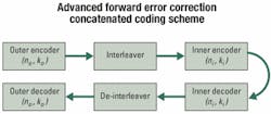
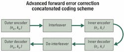
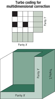
Advanced FEC coding schemes such as concatenated and turbo product codes offer extended performance benefits. Concatenated codes provide an increased coding gain similar to the gain provided by a larger constituent but at a much lower implementation cost measured in terms of lower silicon gate count and area (see Figure 1). Combining codes increases the hamming distance of the two constituent codes with only a linear increase in hardware cost. Proper designing of the code lies in selecting an inner code-the ability to operate at an extremely high input BER-and an outer code, which has more burst-error tolerance but operates at a lower input BER. Such a design allows a combination of codes to be used while incorporating the salient features of each.Building on the performance benefits of concatenated codes, product codes are fully interleaved concatenated codes that allow for multidimensional correction (see Figure 2). For a two-dimensional product code, errors are corrected with iterative sweeps of rows and columns. Errors left previously uncorrected are corrected in subsequent iterations. This technique is generalized under a scheme called turbo-coding because each iteration relies on the result of the previous sweep. Turbo product codes outperform other block codes in their ability to correct for high-input bit-error ratios while maintaining acceptable latency and overhead.
Each of these techniques promises enhanced performance, but some caution is required. Many of these approaches were developed and validated for the wireless industry, where the functioning bit-error ratio is 1x10⁻⁶. One error out of a million bits is insignificant for voice communications, but in 10-Gbit/sec fiber-optic systems, it would allow 10,000 errors per second. In optical systems, functional BER requirements are several orders of magnitude more stringent, which means that at these levels, the likelihood of decoding errors needs to be minimized.
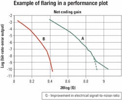
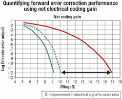
Theoretical models of code algorithms are based on probability theory and approximate the error statistics that can be corrected by specific combinations of codes. The more complicated the code, the more likely it is that the theoretical model will diverge from the true performance. Some FEC algorithms will exhibit error "flaring" at low corrected error rates, which results in lower coding gain than predicted.Figure 3. This simulation plot shows net electrical coding gain versus corrected bit-error rate (BER) for two different Reed-Solomon/Bose, Chaudhuri, Hocquenghem (RS/BCH) product codes. Code A uses a relatively small BCH(248,232) inner codeword, while code B uses a much larger inner codeword. The deviation from the theoretical prediction (shown by the broken line) for code A represents "flaring." The flaring becomes evident starting at 1 x 10e-10 output BER when decoding errors start to dominate performance. The minimum hamming distance of this code causes the curve to flatten.
Flaring in concatenated codes and product codes is related to the hamming distance of the constituent codes. An inner decoder using a small code may produce many decoding errors, behaving like an error generator. Instead of observing the sharp increase in coding gain versus BER as predicted by theory, the performance plot starts to flare, as shown in Figure 3.
Since error flaring is not detected in the theoretical calculation, hamming distance can be used as a proxy for the likelihood of a decoder error. Actual numeric simulation of codes should be used to verify performance, but the time required at 1E-15 BER is prohibitive. Eventually, FEC devices must be measured and verified at their intended BER performance level. The selection and use of advanced FEC depends on several systems- related issues:
- An accurate methodology for measuring and comparing performance must be established.
- Potential impairments caused by increased overhead must be balanced against the benefits of increased performance and associated cost savings.
- As with any technology advancement, availability of compatible components is required for market application.
NECG is commonly used to quantify FEC performance and indicates an improvement in the ESNR at the receiver due to FEC while accounting for the increased noise bandwidth required by the added parity. Since the increased line rate requires wider bandwidth electronics, the result is an additional noise-bandwidth penalty at the receiver. NECG is computed as follows:
NECG(dB) = 20log(Qout)
- 20log(Qin) - 10log(n/k).
Qout and Qin represent the output and input ESNR, respectively, while 10log(n/k) represents the noise-bandwidth penalty. Figure 4 provides a graphical representation.
Inadequate compensation of chromatic dispersion can also account for the bandwidth penalties at higher FEC rates. Dispersion compensation is highly dependent on system design. The dispersion penalty between standard RS(255,239) FEC at 10.7 Gbits/sec and a high-performance FEC at 12.5 Gbits/sec can vary between 0 and 0.6 dB, depending on how the compensation is managed within the system. This impairment is relatively small, considering the 2-3-dB NECG improvement provided by advanced FEC over standard FEC.Nonlinear optical effects such as scattering, self-phase modulation, and four-wave mixing can lead to increased signal distortion as a system's optical power is increased. On the other hand, lowering optical power levels results in a reduced OSNR at the receiver. Advanced FEC can effectively address both of these problems by maintaining acceptable OSNR, or Q, without increasing optical power.
Currently, vendors offer physical layer components at networking rates of up to 12.5 Gbits/sec to meet the demands of FEC and advanced FEC implementations. The cost of these components remains the same regardless of bit rate. The availability of optics is a matter of screening and improving yields for most components; therefore, availability is typically high. Several electro-absorption modulator lasers (EMLs) and lithium niobate suppliers as well as receiver vendors offer products that are screened for 12.5-Gbit/sec performance levels in production quantities.
Such devices as avalanche photodiode receivers are more expensive at higher bandwidths, while other components are available at essentially the same cost. These issues are related to system design and implementation, but generally component costs increase line-card costs by only 2-5% over the cost of a 10.7-Gbit/sec line card.
Additional net coding gain
System gains from FEC offer network operators significant performance and economic benefits. A single-decibel increase in NECG is equivalent to higher OSNR, which can be used to increase DWDM channels or span distances by about 12%. Further, reducing the number of optical amplifiers in a system offers significant cost savings.
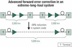
The longer the link, the more value FEC can add to a system. Consequently, adding 1 dB to a 1,000-km link has more value than adding 1 dB to a 100-km link. The savings become more dramatic with advanced FEC, which is equivalent to providing nearly a 50% increase in optical power compared to standard FEC. Figure 5 demonstrates the benefit of advanced FEC for next-generation ELH system implementations.
Future development
Researchers improved on block codes to come up with concatenated codes. In a similar manner, they are actively pursuing better, more efficient FEC algorithms that can provide high error-correcting capability with low overhead. But care must be taken to verify low corrected BER performance with simulation or measurement to account for potential problems with these high-powered codes. Clearly, advanced FEC solutions offer a bottom-line benefit that supports short-term implementation; a better understanding is needed of the development cycles and lengths of network build-out in the future. A common area of interest among the development community is low-density parity-check codes, which hold the promise of performance approaching the theoretical limits of correction power with a given overhead called the Shannon limit.
Another area of active development is "soft decision" FEC. Current FEC approaches make decisions based on "hard" 0 or 1 values. Soft decision FEC uses multiple decision levels by incorporating an analog-to-digital converter into the receiver. Providing the FEC algorithm with multiple levels at the decision point results in more powerful error correction capability and increases the Shannon limit with respect to hard decisions.
Apoorv Srivastava is a project manager, Avinash Velingker is a senior systems engineer, and Steve Rood Goldman is product manager, FEC products, at Multilink Technology Corp. (Somerset, NJ).
